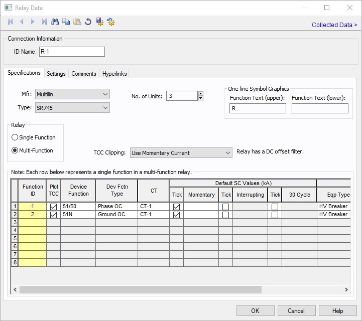
Figure 1: Relay Data Dialog Box
This dialog box includes the following areas and tabs:
See Common Tabs for information on the Location, Comments, Hyperlinks, Media Gallery, or Collected Data tabs.
Figure 1: Relay Data Dialog Box
| Option | Description |
|---|---|
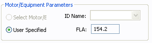
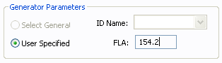
| ID Name |
Uniquely identifies the equipment item. The program automatically assigns a name, but you can change it, if needed. The name can be up to 16 characters long. For relays, the program automatically assigns the names R-1, R-2, R-3, and so on. |
| Group Name/Type | If the relay is part of a functional group, the group name and type appears here. See Functional Groups. |
|
Device No. |
Description |
Suffix |
Description |
|---|---|---|---|
|
46 |
Phase Balance Current Relay |
P |
Phase |
|
49 |
Thermal Relay |
G |
Ground |
|
50 |
Instantaneous Overcurrent Relay |
N |
Neutral |
|
51 |
Time Overcurrent Relay |
Q |
Negative Sequence |
|
51/50 |
Time and Instantaneous Overcurrent Relay |
IAC |
IAC Curves |
|
67 |
AC Directional Overcurrent Relay |
IEEE |
IEEE Curves |
|
79 |
AC Reclosing Relay |
IEC |
IEC Curves |
|
87 |
Differential Protective Relay |
DT |
Definite Time Curves |
|
Device No. |
Description |
Suffix |
Description |
|
46 |
Phase Balance Current Relay |
P |
Phase |
|
49 |
Thermal Relay |
G |
Ground |
|
50 |
Instantaneous Overcurrent Relay |
N |
Neutral |
|
51 |
Time Overcurrent Relay |
Q |
Negative Sequence |
|
51/50 |
Time and Instantaneous Overcurrent Relay |
IAC |
IAC Curves |
|
67 |
AC Directional Overcurrent Relay |
IEEE |
IEEE Curves |
|
79 |
AC Reclosing Relay |
IEC |
IEC Curves |
|
87 |
Differential Protective Relay |
DT |
Definite Time Curves |
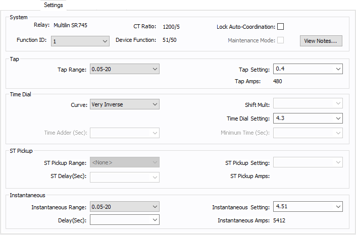
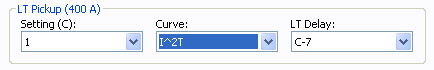
Figure 4: Relay Data - Settings Dialog Box
Some relays have settings and time current curves just like the low voltage breaker solid state trip devices. The common type is direct action trip (DAT) units found in some medium voltage breakers. The settings tab for these relays has a slightly different layout as described below.
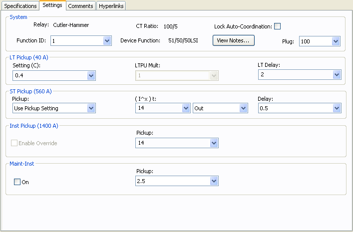
Figure 5: Relay Data – Settings Dialog Box for DAT
See Common Tabs for information on the Location, Comments, Hyperlinks, Media Gallery, or Collected Data tabs.
| Database Technical Reference | Common Tabs |
| Media Gallery |
|
|