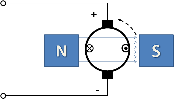
Figure 1: DC Motor
This section describes DC models you can use in EasyPower and describes the analysis results.
Please note the following about short circuit results:
Figure 1: DC Motor
The simplified electrical characteristic of the DC motor can be described by the following equation:
Vt = Ea + Ia * Ra
Where,
Vt = Terminal voltage
Ea = Induced armature voltage (back e.m.f.)
Ia = Armature current
Ra = Armature resistance
The factors affecting the induced armature voltage are:
DC motor starting: While starting DC motors, speed is initially zero and so Ea is zero. As a result, the starting current is high. The starting current can be calculated from the equation:
DC motor short circuit contribution: The speed is assumed at rated speed, so Ea is close to the system voltage. The terminal voltage Vt collapses to near zero for fault near the terminal. The negative sign represents current flow out of the motor.

The impedance Ra is used as the short circuit model in the calculations.
Motor Data: HP = 100; V = 250; Efficiency = 95%; Ra = 0.05 ohms
FLA = Input kW / V = HP * 0.746 / (Efficiency * kV)
= 310 Amps
Starting Current = V / Ra
= 250 / 0.05 = 5000 Amps
Starting Resistor to limit current to 4 x FLA:
Rtotal = Ra + Rstart
Rtotal = V / (4 x FLA) = 250 / (4 x 310) = 0.20 ohms
Rstart = 0.20 – 0.05 = 0.15 ohms
Short Circuit Contribution to terminal fault:
~ 250 / 0.05 ~ 5000 Amps
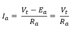
It is best to use the armature resistance from the manufacturer if it is available. The armature resistance needs to include the commutator resistance. In the absence of exact information, we can make some assumptions. The graph below shows the calculated percent impedance of a few DC motors obtained from a facility.
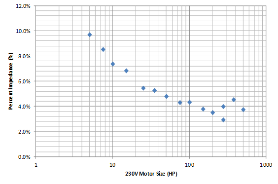
Figure 2: Calculated Percent Impedances for Sample 230V DC Motors
For a motor rated at 50HP, 230V, 0.9 efficiency, we will estimate the armature resistance. For this example, assume 8% impedance. This is how much voltage drop there is across the armature and commutator at full load.
Vdrop = 8% of 230V = 18.4V at FLA.
FLA = 0.746 * HP / (Efficiency * V) = 180A
Ra = Vdrop / FLA = 18.4 / 180 = 0.1 Ohms
A battery is modeled as a voltage source and a series resistance (internal resistance). This is true for both short circuit and power flow analysis.
Figure 3: Battery Electrical Model
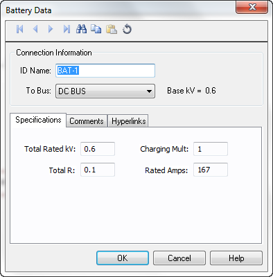
Figure 4: Battery Dialog Box
| Option | Description | ||||||||
|---|---|---|---|---|---|---|---|---|---|
| Total Rated kV | This is the total voltage rating of the battery string. If you have multiple batteries connected in series, add up the voltage of individual batteries. For parallel connection for similar batteries, leave the voltage as is. | ||||||||
| Charging Multiplier | This is multiplier for the battery voltage reflecting the charge condition. For example, a fully charged battery could have 1.05 and a slightly drained battery could have 0.95 as the charging multiplier. | ||||||||
| Total R |
This is the internal resistance of the battery string in ohms. You can get the internal resistance from the manufacturer. Here is some typical data for batteries:
Reference: http://www.solar-electric.com/agm-battery-technology.html |
||||||||
| Rated Amps | The rated (nominal) amperes of the battery or battery string. The nominal amp rating is the ampere-hour divided by the discharge time for such batteries. For example, if you have a 200Amp-hour battery rated at a discharge time of 8 hours, the rated amps is 200 / 8 = 25A. |
A flooded lead acid battery has a rating of 250V and 200Amp-hour with a discharge time of 8 hours. Estimate the resistance of the battery.
Rated Amps = 200 / 8 = 25A.
We will assume 10% impedance for this case.
Total R = V * (% Impedance) / (Rated Amps) = 250 * 0.1 / 25 = 1 Ohm.
Multiple identical cells or batteries can be connected in series, in parallel, or in a combination of both.
If you have the impedance in percent, there is no need to add or divide the percent value. You can calculate the resistance based on the final voltage and current capacity.
The graph below shows an approximation of the V-I characteristics of photovoltaics. This is nonlinear and is used when solving power flow. As the load demand increases beyond the capacity of the photovoltaic, the voltage drops rapidly.
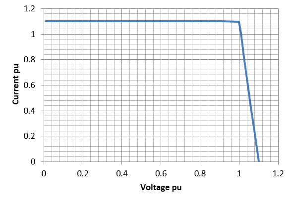
Figure 5: V-I Characteristics of Photovoltaics
The characteristics are derived from the user defined inputs in the dialog box. The important data include:
For more information about photovoltaics, see Example 3: Photovoltaic System.
NFPA 70E, Edition 2015, Annex D.5 describes the method for calculating arc flash hazard energy for low voltage DC equipment. This method is based on the maximum power transfer theorem similar to Ralph Lee's method for AC.
Iarc = 0.5 * Ibf
Ei = 0.01 * Iarc * V * t * Factor / D2
Where,
Iarc = estimated DC arc current in amps
Ei = estimated incident energy in cal/cm2 at the working distance D
V = DC voltage in volts
t = arc duration in seconds
D = working distance in cm
Factor = 1.0 for open air and 3.0 for enclosures (box)
| DC in EasyPower | Example 2: DC Link Inverter with a Battery Bank (UPS) |
| Tips on Creating DC Systems | Example 3: Photovoltaic System |
| Example 1: Sample DC System |
|
|