Arc Flash Hazard Tab
To set short circuit options, from the Short Circuit focus, click SC Options.
On the Arc Flash Hazard tab, select the options to control your arc flash hazard analysis.
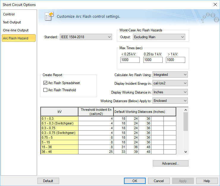
Figure 1: Short Circuit Options – Arc Flash Hazard tab
| Option | Description |
|---|---|
|
Standard |
You can select any of the following standards for calculation method.
This method is based on the IEEE 1584-2018 Guide For Performing Arc Flash Hazard Calculations, a revision of the original publication in 2002. The arc flash hazard calculations are dependent upon equipment voltage, bolted fault current, arc time, electrode gap, electrode configuration, and enclosure size. Selection of the calculation method for systems outside of the IEEE model range is available in the Advanced Arc Flash Options. See Advanced Arc Flash Options for more information. This method is based on the IEEE 1584-2002 Guide For Performing Arc Flash Hazard Calculations and includes amendments 1584a-2004 and 1584b-2011. The arc flash hazard calculations are dependent upon equipment voltage, bolted fault current, arc time, electrode gap, equipment type and system grounding. NFPA 70E-2018 Standard for Electrical Safety in the Workplace references this calculation method in Annex D.4. The Ralph Lee method is applied where system voltage exceeds 15 kV. In NFPA 70E, Annex D provides summarizes calculation methods available for calculating arc flash boundary and incident energy. These are empirical equations based on arc flash tests. The arc energy is dependent on the variables bolted fault current, arc time, and enclosure type. The Annex references equations from a paper published in 1998 by R. L. Doughty, T. E. Neal and H. L. Floyd, II. Refer to the standard or the original paper for details on the calculation method. The V7.0 Enhanced equations are based on the IEEE 1584-2002 equations. Close examination of the IEEE 1584-2002 equations revealed that, in a few cases, unexpected results occurred. For example: Due to these types of issues, EasyPower developed a set of Enhanced arc flash equations that were similar to the IEEE 1584-2002 equations, but addressed these and other concerns. Based on engineering judgments and comparison with test data from the industry, the results from the Enhanced equations appear to be more reasonable than the IEEE 1584-2002 over a wide range of bolted fault currents and system voltages. However, users should be aware that the Enhanced models cannot be guaranteed to be more accurate than the IEEE 1584-2002. The Enhanced method is intended to be a tool used to assist in the selection of protective clothing for workers who may be exposed to arc flash. The V6.0 Enhanced equations pre-dated the V7.0 Enhanced equations. If you choose to use the Enhanced equations, it is recommended that the V7.0 Enhanced be used. The V6.0 Enhanced equations are included for archival purposes only. |
|
Worst-Case Arc Flash Hazards |
|
|
EasyPower obtains the arcing time from the upstream protective device of the faulted bus. The program uses the coordination feature PowerProtector™ to calculate the trip time for the estimated fault current passing through the protective device. This is the most accurate method. This option works only if you have the PowerProtector™ feature included in your EasyPower software. |
|
|
Output |
Select one of the options to evaluate the arc flash hazard results for any bus in the following ways:
Note: Panels typically have the main breaker, bus bar and feeder breakers housed inside the same enclosure. Opening the front cover would expose a worker to arc on the line side of the main breaker. To simulate this hazard, select the Excluding Main option, since the device to interrupt faults would have to be an upstream device. |
|
Use the worst case arcing currents |
This option is not applicable to IEEE 1584-2018. IEEE 1584-2002 recommends using two scenarios – one with 100% of estimated arc current and the other with 85% of estimated arc current. This is due to the fact that arc currents may be random and usually vary by some proportion about the estimated value. For inverse-time over-current characteristics of protective devices, the arcing time is greater for smaller currents than it is for larger currents. Since the incident energy of arc faults is more sensitive to arcing time than it is to arc currents, it is necessary to obtain a more accurate arcing time. IEEE 1584 proposes taking 85% of the initial estimate of the arc current. EasyPower enables you to consider two scenarios of arc currents. EasyPower calculates both scenario and automatically reports the worst case of incident energy, thus providing conservative results. The IEEE 1584 recommended 100% and 85% of arc current are default values. You may change these ratios by typing in the fields or using the buttons to increase or decrease the values. When 100% or the upper value yields greater arc flash incident energy, then the text results are displayed in black in the Arc Flash Report spreadsheet. When 85% or the lower value yields greater incident energy, the text is displayed in pink. |
| Max Times (sec) |
The Max Time is the maximum time that the program uses to calculate the incident energy. If the trip time calculated as per device TCC is less than the specified maximum time, then the device trip time is used. If the device trip time exceeds the specified maximum time, then the Max Time value is used. The default maximum time is 1000 seconds. |
| Calculate Arc Flash Using |
Specify the fault current used during arc flash calculations. Select between Momentary, Interrupting, and 30 Cycle fault currents or the Integrated method. See The Integrated Method for more information about this method. |
| Display Working Distance in |
You can select the units for working distance from any of the following. This also affects the arc flash boundary.
|
| Working Distances (Below) Apply to |
You can specify separate working distances for open air and enclosed space. Select the appropriate choice to view or edit the values in the spreadsheet. Typically for medium voltage, switches and fuses at open air may be operated from a greater distance. In the Enclosed table, there are separate working distances for switchgear. This enables you to specify a different working distance for switchgear than for other types of equipment. |
|
Display Incident Energy in |
You can specify whether you want incident energy displayed in calories or joules per square centimeter. |
| Create Report | |
| Arc Flash Threshold |
Check this box to obtain a report of buses that exceed the arc flash threshold incident energies specified in the options. You can specify any incident energy as the threshold for various voltage levels by typing in the values in the spreadsheet in the Arc Flash Hazard options. All equipment exceeding the hazard thresholds will be displayed in red on the one-line. |
| Threshold Incident energy |
For every voltage level you can specify the threshold incident energy. Equipment with incident energies exceeding the threshold values will be highlighted in red in the one-line output and they will be reported in the Arc Flash Threshold Report. This provides instant notification of a danger condition. All equipment with incident energies exceeding the threshold values are displayed in red on the one-line. |
| Default Working Distances |
For every voltage level, you can specify up to five working distances for which the incident energy will be provided in the Arc Flash Report. In the one-line output, results will be shown only for the shortest working distance, which has the highest incident energy. |
|
Advanced |
|
More Information
| Short Circuit Options (ANSI) | TCC Options |
| Short Circuit Reference (ANSI) | SmartDuty™ |
| Faulting a Bus | Controlling the Analysis |
| Voltage Sensitivity Studies |
|
|