Viewing Remote Voltages and Currents
For protective device coordination or relay setting studies, it is necessary to know voltage and current in parts of the system that are remote from the fault. This is especially true when you are studying backup relaying, voltage sensitive devices, or generator relaying. EasyPower lets you easily study these parameters by clicking the toolbar.
To see a remote voltage and current after you perform a fault, first select the buses you want to view, and then click  Remote V&I.
To view remote bus voltages and currents for all buses, click  Remote V&I without selecting any buses.
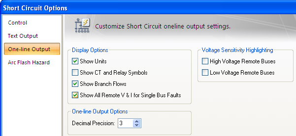
Note: You can also select Show All Remote V & I for Single Bus Faults from the One-line Output tab Short Circuit Options dialog box.

Figure 1: Option to Show Remote V & I

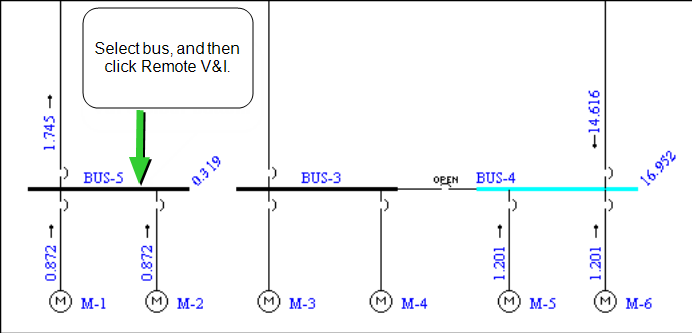
Figure 2: Showing Remote Voltage and Current
Voltages for each bus and the currents for each branch connecting to the bus are displayed. In this example, 0.872 kA from each of the motors flow to the fault on BUS‑4. For remote buses, the voltage is shown to the right of the bus at an angle. At BUS-5 in the example above, the value is 0.319 per-unit, or about 32 percent of nominal.
This operation can be done any number of times in succession for one or more selected buses. When a new fault is performed, the old results are automatically cleared.
For ANSI, we show line-to-line voltages for 3-phase faults. Unbalanced faults show line-to-neutral voltages.
Note: Remote voltages and currents are only available after a fault operation on a single bus.
More Information
| Short Circuit Reference (ANSI) | |
| Short Circuit Options |

|