Notes on Photovoltaic Specifications
Care should be taken to specify data correctly for a Photovoltaic equipment item in EasyPower. The data items should correspond directly to an actual VI curve for a Photovoltaic panel. For example, a curve could be as follows:
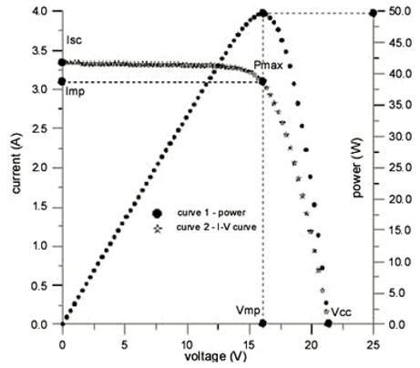
Figure 1: Characteristic Curve of Photovoltaic Model
For this curve, we see that for this panel, we have:
VMP V at Maximum Power 16 V
VOC V at Open Circuit 21 V
ISC I Short Circuit 3.3 A
This curve has been simplified in EasyPower as follows:
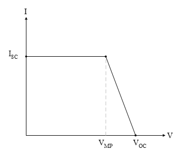
Figure 2: Simplified Photovoltaic Curve Formula
For this simplified approach, the maximum kW would then be calculated as:
kW Max = (ISC)(VMP)
This simplified curve is used in the PF Engine to simulate the Photovoltaic. Thus, as terminal voltage of device drops from VOC down to VMP, the power output of the device will increase. As the voltage drops below VMP, power decreases to near zero when V = Zero. To properly get solutions under a number of circumstances (i.e. voltage conditions, and other DC Load Types on the same DC system the Photovoltaic is connected to) there are a number of algorithmic additions made.
Now, in most cases, one should make the defined DC Bus rated Base kV equal to VOC for an entire string of panels that have been hooked both in series or series and parallel. In EasyPower, we do not have any method for representing a set of series connections, and so we must rely upon specifying a series string as the lowest common denominator. In this way, we get the VOC definition at the voltage that will be applied to the Inverter, and many strings (each represented by ONE (1) EasyPower Photovoltaic equipment item) can then be put in parallel to generate a total Photovoltaic array.
Test Case 1
A couple of example systems have been built that show such construction. The first is Photo Voltaic – Large Array.dez. This case creates a single a Photovoltaic Array up to a single Inverter where each EasyPower Photovoltaic equipment item is a string of panels defined by:
Max Power: 2.7 kW
VMP 0.38 kV
VO C0.43 kV
ISC 7.5 A
This data was extracted from a paper documenting a Photovoltaic power plant in Tucson, Arizona (Photovoltaic Power Plant Experience at Tucson Electric Power. Larry Moore, Hal Post, Tom Hansen, and Terry Mysak). Notice that the base voltage for all DC Buses is defined at 0.43 kV, which is the open circuit voltage for the series string.
Solving the system in the PF Focus will reveal all DC Buses highlighting red due to voltages dropping below the default 0.95 pu under-voltage threshold for display. A quick check on the ratio of VMP / VOC shows that the voltage at maximum power is 0.38 kV / 0.43 kV which is 0.88 pu. Thus, you should expect the voltage to be somewhere near this value when at maximum power.
Now since this case has the Inverter specified at 125 kW, after some testing with the case, you will find that when the specified power of the Inverter (the kW field in the Inverter PF Tab) is such that the voltage on its input bus drops below the Minimum Voltage Threshold (the Minimum Voltage Threshold field in the Inverter PT Tab), that the Inverter will back off its power requirement in steps until that is met. This special behavior is described further below.
For this test case, the Minimum Voltage Threshold was set to 0.9 pu, and thus the loading was not allowed to reach the maximum capability of each string. Note that the power flow solution also included all of the losses in the DC distribution equipment so that the power at the Inverter input should be equal to All Photovoltaic Outputs + DC Cable Losses.
Running short circuit fault simulations reveals how each Photovoltaic produces the output current specified as ISC. Since the EasyPower fault calculation method is classical and based on an injection method, this current output is completely dependent upon DC Cable impedances being small. If the Cable impedances become significant compared to the equivalent internal fault resistance of the Photovoltaic, you will see a reduction in the Photovoltaic’s output current under fault conditions.
Test Case 2
The second test case is Photo Voltaic – Large System.dez. This case uses one Photovoltaic equipment item to represent an entire array connected to a single Inverter. In such a case, we are more interested in the AC distribution system than we are in the DC distribution system, as modeled in detail in the first test case. If wanted, the full detail of the array could be substituted into for each single Photovoltaic equivalent. That would produce a case with extensive detail. That is left for the reader to experiment with.
More Information
| Photovoltaic Data |
|
|