Notes on Photovoltaic Power Flow Modeling
During a power flow solution, the photovoltaic considers the two voltage conditions that have a shutdown and limiting effect. These conditions need to be automatically handled during a solution so that reasonable solutions can be reached. These conditions typically happen when the photovoltaic system and the load demanded of it, or the voltage conditions applied to it are not in line with normal operating conditions.
A Photovoltaic has the ability to be the single source that allows a system to enter power flow and solve the system.
The Photovoltaic Has a Terminal Voltage Greater Than VOC
For this condition, we force the Photovoltaic current output to zero. If this were not controlled, the device would go into a reverse power condition which does not follow after the photovoltaic characteristic.
The Photovoltaic Terminal Voltage Is Less Than VMP
For this condition, we need to limit the photovoltaic output current to ISC. We typically get into this condition when:
- There are no inverters in the model being fed by this photovoltaic, and we need to current limit to properly simulate a DC system with other DC sources and other DC loads.
- An inverter being fed by this photovoltaic has reached a condition where it cannot lower loading any more, and so the voltage drop cannot be improved.
Note that this current limiting is typically active only when:
- There are no inverters being fed by this photovoltaic.
- The inverter fed by this photovoltaic has already limited out on its load reduction in an attempt to keep DC input voltage above the inverter Minimum Voltage Threshold.
Photovoltaic Loading 1
When building a DC system that has Photovoltaics AND Loads, care should be taken to specify the Loads properly. Photovoltaics prevent a power flow solution if the voltage on the Photovoltaic drops below a threshold (defaulting to 0.4 pu bus voltage). Testing has shown as the voltage drops on a DC system with Photovoltaics that a run-away voltage collapse condition can occur due to inappropriate load specification. An automatic check is made on the Photovoltaics so that when voltage reaches a severe under-voltage condition (actually an impractical condition due to desiring to always extract maximum power out of a Photovoltaic array) during the power flow solution, the solution is terminated for this unreasonable condition.
We recommend the load be specified as Constant Impedance so that loading drops with a drop in DC voltage. If the load is specified as Constant Power or Constant Current, then loading can actually increase as voltage drops, thus causing an additional drop in the DC voltage at the Photovoltaic. When using Constant Power or Constant Current loads, great care should be taken to properly specify the load to match the output capability of the Photovoltaic.
Photovoltaic Loading 2
When a Photovoltaic is used with an Inverter, care must be taken to properly specify the kW set-point of the Inverter so that the Photovoltaics feeding the Inverter are loaded properly. If the Photovoltaics are loaded beyond their capability, such that their terminal voltage falls below VMP, their loading capability drops according to their defined VI Curve. If this power output drop continues while the Inverter continues to demand the same power during the power flow solution, then the power draw (a constant power load) of the Inverter obviously cannot be met. The power flow solution fails in this condition. The setting Min Voltage Threshold is supplied with the Inverter model to allow for automatic load reduction of the Photovoltaic systems (stepping the kW set point down on each iteration as needed to drop load so a power flow solution can be reached).
Photovoltaic Minimum Voltage Limit
This limit is specified in the Registry, and defaults to a value of 0.4. It is used to terminate the power flow solution if the terminal voltage on a Photo Voltaic drops below this setting. The condition of extreme low voltage typically occurs when a Photovoltaic is supplying a constant power load that cannot be met by the Photovoltaic. Voltage proceeds to drop, and the solution spirals into a voltage collapse condition.
Name: PFPVMinVoltSolnLimit
Location: Options
Type: DWORD
Represents: Value in percent
Default: 40
Example: A value of 40 is 40% which is 0.40 pu voltage in the engine.
Photovoltaic Voltage Reduction Acceleration
This setting is used to accelerate the voltage reduction on a Photovoltaic for a condition where the terminal voltage of the Photovoltaic has dropped below VMP, and we need to hold ISC. In this condition, the power flow solution is dropping the Photovoltaic’s internal voltage model on each iteration by:
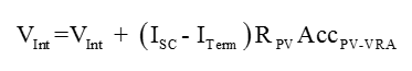
where:
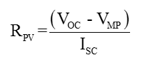 and AccPV-VRA is this registry variable.
Name: PFPVVoltReductionAcc
Location: Options
Type: DWORD
Represents: Values in percent
Default: 300
Example: A value of 300 is 300% which is 3.0 pu in the engine.
More Information
| Photovoltaic Data |
|
|