Notes on Rectifier Modeling
DC Rated kV
When simulating a DC system that connects to an AC system via a Rectifier, then the proper Rated DC voltage needs to be specified for the Rectifier. The DC voltage is related to the AC voltage under no load conditions as follows:
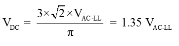
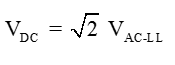
This equation is for a 6-pulse rectifier and includes the ripple on the DC bus, and is typically used on DC systems that do not include a large smoothing capacitor; systems such as HVDC and simple large rectifiers. If you know that the DC bus includes a DC bus capacitor, and that under loaded conditions ripple is minimal, you should use:
Mandatory Commutation Impedance
When a Rectifier is specified as either Diode or Thyristor, a mandatory commutation impedance must be specified on the Power Flow tab. This impedance is used to calculate terminal conditions on the input of the Rectifier according Kimbark’s Equations. In addition, we mandate a transformer be placed upstream of the Rectifier that has the exact same impedance specification as the commutation impedance. This is the reason why the commutation impedance specification in the Power Flow tab is specified just like a transformer; so that there is a one-to-one correspondence. Kimbark’s equations have been written with a basis in high voltage DC lines, which always incorporate an isolation and voltage transformation transformer from the AC line voltage where the converter is specified, and the converter itself. Thus, to use the equations, there must always be a converter-transformer pair, or the equations are not correct for the model.
Note: Specification of Diode is modeled as Thyristor with Alpha forced to zero at all times. Thus, Kimbark’s equations are used for all Diode modeling.
Parallel Rectifiers and Short Circuit
If parallel rectifiers are not connected to the same bus and they have two independent parallel paths that supply a summing fault contribution, the total fault contribution is the total of the two sources as defined by their Times FLA value. This is an adequate approximation for all rectifier types.
However, if you have two Diode or Thyristor rectifiers in parallel, and they have the same supply side transformer, then the total short circuit on the DC side will not be represented correctly, as their Times FLA values represent two independent rectifiers. The short circuit current on the DC bus will be nearly double what it actually is if the rectifiers are the same size. The paralleled converter resistance plays very little part in the fault level, which is controlled mostly by the single up-stream supply transformer.
For example, if you have two diode rectifiers in parallel with independent supply transformers, then the short circuit on the output will be an excellent representation.
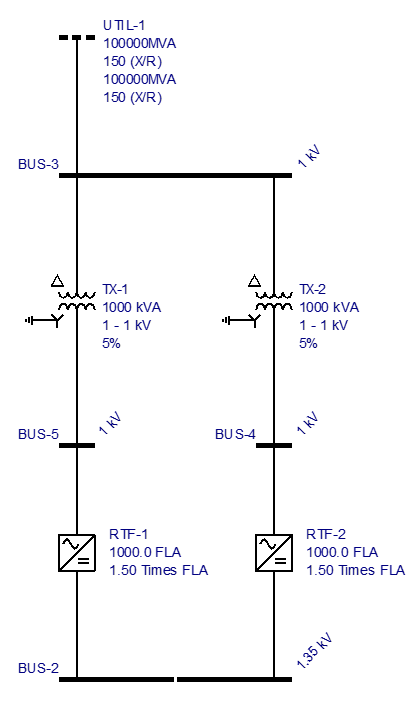
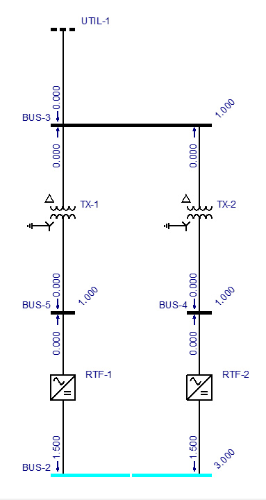
Figure 1: Acceptable representation if Times FLA for each rectifier is determined independently
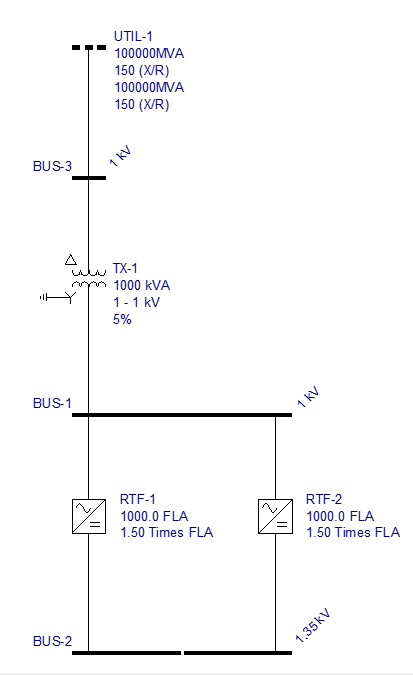
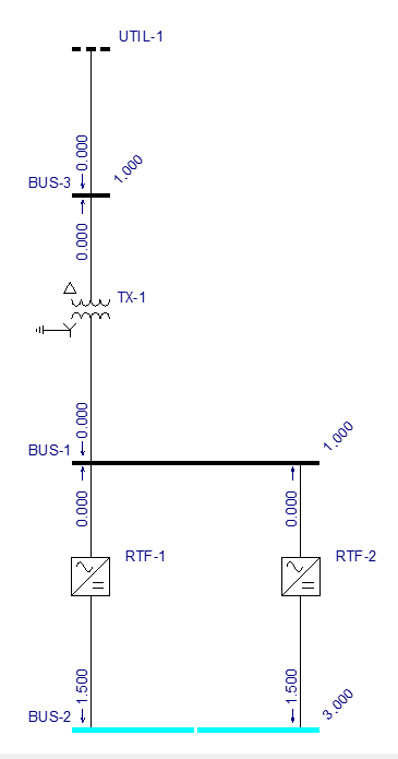
Figure 2: Inaccurate representation, since the total fault current is NOT the sum of the individually determined Times FLA values for the two rectifiers.
More Information
| Rectifier Data |
|
|