Performing Auto Design
Prerequisites for Auto Design
Before you can perform auto design, you need to create a basic one line. The following items are required or recommended:
- The one-line must have a source (utility or generator) connected.
- Define all the loads and motor HP. Upstream cables and protective devices can be sized based on downstream loads or the downstream bus rating. In the absence of load data, you can also specify the Amp rating for the downstream bus items like panels.
- For motors, make sure that the motor size (HP) and rated voltage is a standard/typical size. All motors sizes described in NEC are included in the Generic design template. For motors with different HP rating, you will need to include the motor data in the library.
- Define cable lengths. Lengths can affect project quantities and costs, and also affect voltage drop calculations at the downstream end. Cables with undefined length can be given a predefined length specified in Auto Design Options.
- Define bus type. For every bus equipment that needs to be sized, you need to define the type as switchgear, switchboard, panelboard, MCC, panel, and so on. Sizing of bus and the protective devices on the bus is based on the type of equipment.
- Check transformer kV. The primary and secondary kV and the size (kVA) of the transformer must be defined in the design sheet in the library. Typical sizes and voltages are listed in the Generic template. You can add new types of transformers.
Sizing Equipment on One-line
To size any equipment:
- Select the equipment on the one-line. The selected equipment turns green.
- From the Home tab, click
 Auto Design.
 - View the Auto Design report by clicking
 Window on the Home tab and then selecting Auto Design Report. Read the comments to verify the item was sized successfully. The report informs you if there were issues such as insufficient data. See Prerequisites for Auto Design for guidelines.
You can also view the new size of the equipment through equipment data dialog by double-clicking on the item.
Sizing Individual Circuits in MCC and Panel Data
To size individual circuits in MCC or Panel Data:
- In the Description tab of the Panel Data dialog box, in the View list, select Detailed – Both Sides.
- In the Description tab of the MCC Data or Panel Data dialog box, right-click on the row for which you wish to size the cable and protective device.
- From the context menu, select Auto-size Prot Device and Cable. A message similar to the one shown below is displayed.
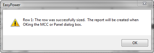
Figure 1: Auto Sizing Successful Message
Sizing MCCs and Panels
On the one-line, right-click on the MCC or panel you wish to size. From the context menu, select Auto Design, and then select the desired option.
- Size Everything: Main fuse or circuit breaker, bus, and all types of outgoing feeders.
- Bus, Main and Main Feeders: Main fuse or circuit breaker, bus, and only those feeders that supply to other MCC or Panels.
- Bus and Main: Main fuse or circuit breaker, and the bus are sized.
- Bus Only: Only the bus is sized.
- Main Only: Only the main fuse or circuit breaker is sized.
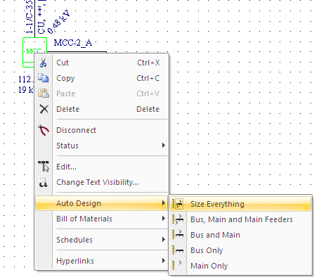
Figure 2: MCC and Panel Auto Design Options
Lock Auto-Sizing
For equipment that can be auto-sized, you can also disable auto-sizing by selecting the check box Lock Auto-Sizing in the equipment data dialog. This is recommended to avoid accidental auto-sizing. You can manually change the equipment data even if the check box is selected.
More Information
| Auto Design | |
| Design Library | |
| Reports |
|
|