Control Tab

To set short circuit options, from the Short Circuit focus, click SC Options.

On the Control tab, specify the options you want for controlling the behavior of a short circuit study.

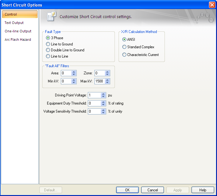
Figure 1: Control Tab of the Short Circuit Options Dialog Box

Option Description
Fault Type

Four different types of faults are available during a short circuit analysis. The default is 3 Phase which is generally used to determine the highest available currents for equipment duty comparisons, and relaying. The other types, Line to Ground, Double Line to Ground, and Line to Line are generally used for specialized relaying applications or system troubleshooting.

X/R Calculation Type

Short circuit calculations are based on one of three methods:

  • The ANSI Standard method uses a separate R network for the interrupting duty (2-5 cycle) network to determine a conservative Z/R ratio. This ratio is then used as the Thevenin equivalent fault point X/R ratio for determining the appropriate breaker contact parting time multipliers and NACD ratios. Current and voltage calculations are based on a complex (R+jX) network reduction. Both the momentary (1/2 Cycle) and 30 cycle calculations use a complex network reduction for all voltage, current, and X/R ratio calculations.
  • The Standard (non-ANSI) calculation uses a complex network reduction for all momentary, interrupting duty, and 30 cycle voltage, current, and X/R ratio calculations.
  • The Characteristic Current Method (CCM) calculates the DC component of each branch based on phase angle of the current flowing in it and then sums the DC component in each branch contributing to the fault current. The ratio of the total DC to the total AC is used to determine the equivalent X/R at fault point. Branch current flows having different current phase angles (X/R ratios) will have the current peak at slightly different times before the first-half cycle. To simplify calculations, the DC component is taken at 0.5-cycle for all branches using the expression in equation below.
  • IDC = Ö2 IAC RMS SYM exp (-p /|X/R|)

    After each DC component is determined and totaled, the equivalent X/R ratio is found from the equation below.

    Equivalent X/R = -p/ ln (S IDC / S IAC RMS SYM / Ö2)

    The CCM method provides a conservative approach to obtain the fault point X/R ratio and appears to do the best overall job without being over-conservative.

    Reference:
    Parise G., A new approach to calculate the decaying AC contributions to short-circuit: the ‘characteristic’ currents method; IEEE Transactions on Industry Applications, Vol. 31, No. 1, January/February 1995.

"Fault All" Filters

Enables you to specify a specific bus Area, Zone, and kV Range that to fault and report when you fault multiple or all buses. This type of analysis is useful when you are interested in studying only a specific region and do not need all of the output associated with a full system analysis. This method is common for old-style text programs. In EasyPower, it is just as simple to select the buses you wish to fault from the one-line fault buses. Only the selected buses are faulted.

Driving Point kV PU

System fault point voltage in per-unit. This value defaults to 1.0 per-unit.

Equipment Duty Threshold

Sets the lower limit for flagging breaker violations in SmartDuty™. If the threshold is set to -10 percent, SmartDuty™ will flag all equipment which has short circuit duties within 10 percent of their maximum rating (greater than 90% of their rating).

Note: The ability to automatically check equipment duties during analysis is only available if you have purchased the SmartDuty™ option to EasyPower.

For example, a GE AM-13.8-500 air blast breaker has a momentary and interrupting duty rating of 19.56/37 kA at 13.8 kV. SmartDuty™ provides a warning flag if the current exceeds 17.6/33.3 kA in either the momentary or interrupting rating. If the current exceeds 19.56/37 kA, a violation is flagged.

Note: You must click Equipment Duty from the Short Circuit focus for this field to have any effect on the one-line result output. 
For this field to have any effect for text result output, you must select the Create Equipment Duty report check box in the Text Output tab of the Short Circuit Options dialog box.

Voltage Sensitivity Threshold

Sets the lower limit setting for flagging voltage violations. If the threshold is set to -30 percent, bus voltages lower than 30 percent (70 percent voltage) of the bus' base kV is flagged. This enables you to quickly check for motor contactor dropout, lighting flicker, and so on.

Note: For this field to have any effect, you must select one or more of the Voltage Sensitivity check boxes in the One-line Output or the Text Output tab of the Short Circuit Options dialog box.

More Information

Short Circuit Options (ANSI) TCC Options
Short Circuit Reference (ANSI) SmartDuty™
Faulting a Bus Controlling the Analysis
Voltage Sensitivity Studies