Faulting a Bus
There are three ways to fault a bus. The easiest way is to double-click on the desired bus. A fault will be placed on the bus using the options selected on the Short Circuit tab and in the Short Circuit Options dialog box.
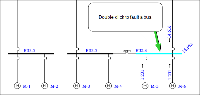
Figure 1: Faulting a Bus
The results are immediately displayed on the one-line. In this example, the faulted bus current is 16.952 kA, which is shown diagonally on the right side of the bus. The contribution from the upstream branch is 14.616 kA, and the motor contribution is 1.201 kA.
To see text results, select the appropriate report and format in Short Circuit Options on the Text Output tab.
Another way to initiate a fault is to first select a bus (the bus will highlight) and then click  Fault Bus(es). You can select more than one bus to fault if desired.
To perform a batch fault of all the buses, click Fault Bus(es) without selecting any buses.
Changing the IEC Standard Time Interval
The following currents can be calculated in EasyPower:
- Initial current: This is the first cycle current. To display results for this current, click
 Initial in the Short Circuit tab.
 - Breaking currents for 0.02 seconds, 0.05 seconds, 0.1 seconds and 0.25 seconds: To display these values, click the corresponding buttons in the Short Circuit tab.
- Steady State: To display the steady state current, click
 Steady State in the Short Circuit tab. Steady state displays the current flow after 0.5 seconds. For three-phase faults, steady state currents are based on the meshed network equations in IEC 60909-0 (84) and (85), where motor contributions are not included in the calculations. For unbalanced faults, motor contributions are included if the C factor is set to Max in the Short Circuit Options. Otherwise, the motor contributions are not included.
You can view up to 3 types of fault current values by time interval.
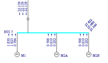
Figure 2: Short Circuit Results at Various Time Intervals
You can also view fault currents in various forms, such as by phase current values (A, B, C) or their symmetrical component values (positive sequence, negative sequence, zero sequence or 3 times the zero sequence).
Displaying Fault Currents by Current Type
You can also display fault currents as symmetrical rms, asymmetrical rms or as peak. To change the display current type, on the Short Circuit tab, click  SC Options, click the One-line Output tab, and then select the desired type in Fault Current, as shown in the figure below. The following choices are available:
- Symmetrical: rms value of AC component.
- Asymmetrical: rms value of AC and dc components combined (total).
- Max Sym and (Max Asym): The maximum phase current amongst the three phases. Both AC symmetrical rms and asymmetrical rms values are displayed, the asymmetrical values appearing in parentheses.
- Max Sym and (Max Momentary Peak): The maximum phase current amongst the three phases. Both initial AC symmetrical rms (Ik”) and peak (Ip) values are displayed, with the peak values appearing in parentheses.
The first three choices are applicable for any time interval, whereas the last choice is only applicable for the initial currents.
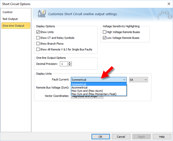
Figure 3: Short Circuit Options for IEC
More Information
| Short Circuit Reference (IEC) | |
| Short Circuit Options (IEC) |