Time-Current Characteristics (TCC) Data
Most of the time-current characteristics (TCC) data are entered in the library as time-current points. A TCC curve may be represented by a number of time and current coordinates. When plotting curves, EasyPower produces smoothed lines passing through these points. The TCC of some relays are based on formulas.
Time-Current Points
Example 1: Relays TCC Data
The figure below is a TCC curve of GE IAC-51 relay for pickup current of 1 amp and time dial setting of 1 second. Ten points have been marked along the curve. The coordinates, or the time-current values of these points, are indicated in parentheses.
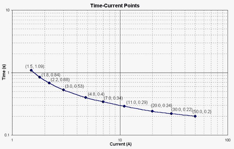
These values are entered in the spreadsheets in Section 2 (Time Dial) of the library as shown in the figure below. The values in the topmost yellow row are the current values. The corresponding time values are entered in white cells. The time values for points shown in the figure above have been entered in Row 2 in the spreadsheet below. The time values for other time dial settings are entered in successive rows. Please note that there is only one row for current values. Therefore, the time values for different time dial settings must correspond to the same set of current values.
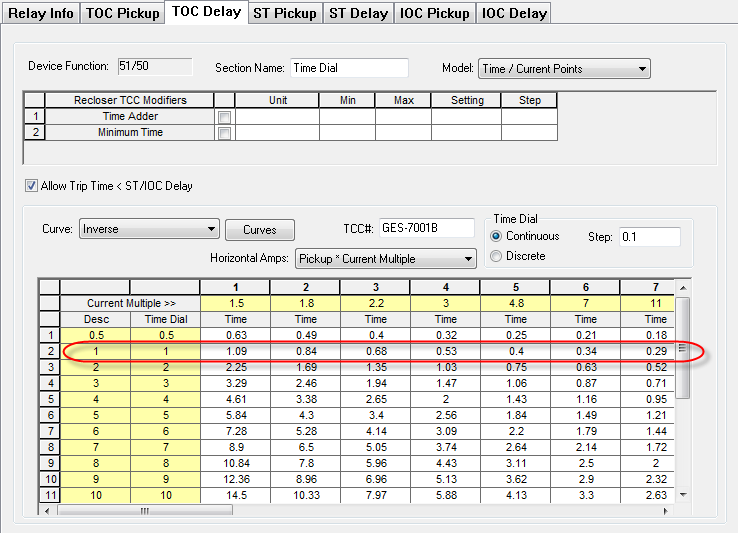
Figure 2: Section 2 (Time Dial) of Relay
Example 2: MCCB Breakers TCC Data
The TCC curve of Square D KAL 70Amp MCCB is shown in the figure below. The units for the current coordinates are in multiples of rated continuous amps. For any given current value, the MCCB may trip at any time between the times shown by Minimum Clearing Curve and Maximum Clearing Curve. The time-current points are shown in parentheses. Any number of points may be obtained for each curve. Typically, 8 to 10 points are sufficient to represent a curve.
The time-current points are entered in the spreadsheet in Section 1 of the MCCB information of the library. The first two columns are for the minimum clearing curve and the last two columns are for maximum clearing curve. You will need to specify the method of calculating the pickup. In this example, the Pickup Calculation is: “Ipu * Trip Amps” because the TCC is given in multiples of rated amps. If the TCC is given in actual trip amps, then Pickup Calculation is “Current in Amps.”
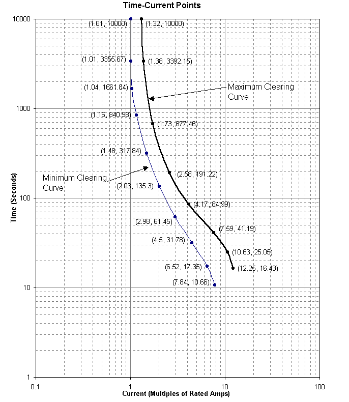
Figure 3: Time-Current Points of Square D KAL 70A MCCB
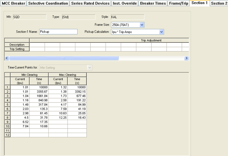
Figure 4: Section 1 (Thermal) Tab of MCCB
Time-current Points of Multi-Segment TCC
Devices such as MCCB, solid state trips, and non-solid state trips have multiple segments in their TCC. In the case of MCCB, the thermal trip data is entered as time-current points, and the magnetic trip data is usually entered separately as instantaneous trip current. However, for an MCCB with fixed (not adjustable) magnetic trip, both the thermal and magnetic TCC data may be entered as a single set of time-current points. In such a case, at the point where the thermal curve intersects with the magnetic curve, duplicate time-current points are obtained. Similarly, duplicate points are taken at any intersection of straight lines with curved lines.
Example 3: Multi-Segment TCC of Square D MCCB EH 100A
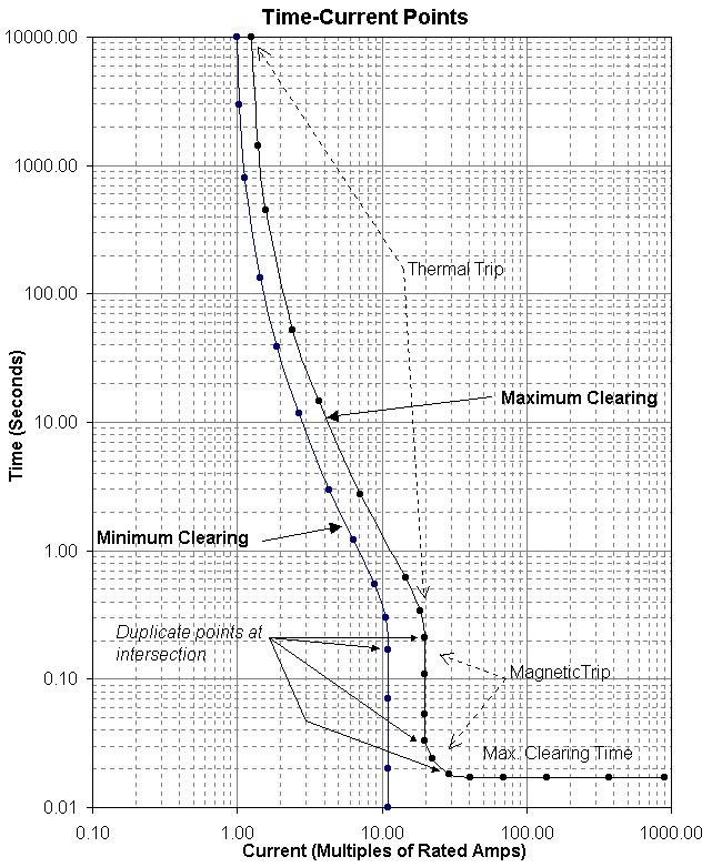
Figure 5: TCC of MCCB with Fixed Magnetic Trip: Square D EH 100A
For the TCC shown above, the intersection points are entered as duplicate points in the spreadsheet shown below. The data for these have been highlighted in gray.
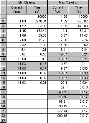
Figure 6: Time-Current Points of Square D EH 100A
TCC Based on Formulas
In some digital relays, formulas are used to generate the TCC. EasyPower includes the following formulas in the library:
To enter TCC data for formulas select the applicable formula name from the Model box in Section 2 of Relay Info as shown in the figure below.
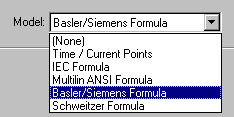
Figure 7: Model Box for Relays
The figure below is an example of the Basler formula. The formula used for calculating the TCC appears below the model name. The values used in the formula are entered in the spreadsheet and edit fields.
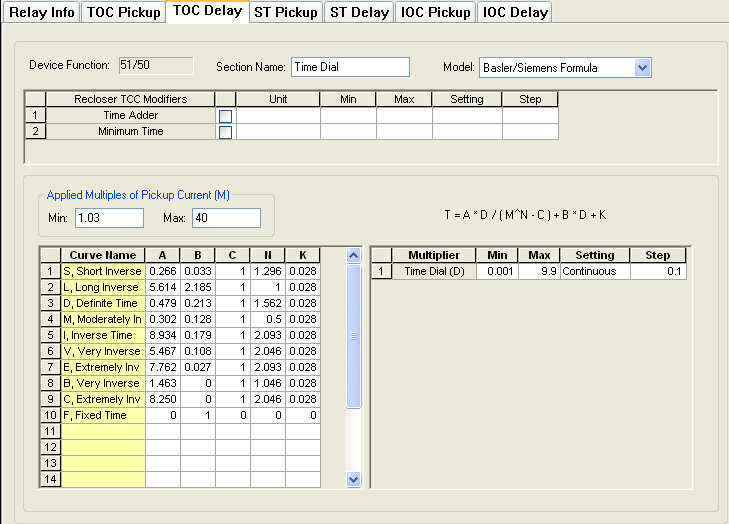
Figure 8: Basler Formula
Adjustable Range for Settings
Protective devices may have adjustable settings for pickup current or the time delay. You may specify any adjustable data range as either continuous or discrete.
Discrete: A range is discrete if there are a finite number of discrete values to which you can adjust the settings. If you select any range as discrete, you must specify all the possible settings available in the rows in the spreadsheet. For example, if the Tap range of a relay is {0.5, 0.6, 0.8, 1, 1.2, 1.5, 2} then select the data range as “Discrete,” and enter the different tap values in separate rows in the spreadsheet called “Values.” Similarly, if time dial of a relay is discrete, select “Discrete” in the dialog box. All the discrete time dial values must be entered separately in consecutive rows in the spreadsheet for time dial.
Continuous: A range is continuously adjustable if it is divisible by a step value. When adjustments are made the setting is incremented or decremented by a multiple of the step value. When you select any range as continuous, you must also specify the step value. For continuous ranges, it is sufficient to provide only two settings: the minimum and the maximum values in the range. For example, if the pickup of a relay is continuously adjustable from 0.5 to 2 with the smallest increment being 0.01, then enter 0.5 as the minimum, 2 as the maximum, setting type as continuous, and the step value as 0.01. When you enter any data range as continuous, EasyPower calculates the intermediate values for the selected setting by interpolation.
More Information
| EasyPower Device Library |