HV Breaker Data
This dialog box includes the following areas and tabs:
See Common Tabs for information on the Location, Reliability, Comments, Hyperlinks, Media Gallery, or Collected Data tabs.
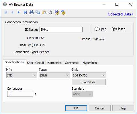
Figure 1: HV (High Voltage) Breaker Data Dialog Box
Connection Information
| Option |
Description |
| ID Name |
Uniquely identifies the equipment item. The program automatically assigns a name, but you can change it, if needed. The name can be up to 16 characters long.
For high voltage breakers, the program automatically assigns the names BH-1, BH-2, BH-3, and so on.
|
| Open/Closed |
Normal state of the high voltage breaker. If Open is selected, the one-line displays “OPEN” next to the high voltage breaker symbol. If Closed is selected, the one-line symbol does not display any text. |
| On Bus |
The bus to which the high voltage breaker connects, which must already exist on the one-line. For your reference, the On Bus base kV is displayed next to the bus name.
|
|
Phase
|
The phase of the item. Currently, this is for reference only.
|
| Connection Type |
Whether the high voltage breaker is connected as a “Feeder,” (such as to a cable, busway, transformer) or as a “Tie” (between two buses). |
Specifications Tab
| Option |
Description |
| Mfr |
Provides a list of manufacturers available in the device library. If the desired manufacturer is not listed in the device library, you can add it to the library.
If the desired manufacturer is missing from the list, choose Other.
|
| Type |
Equipment types available from the selected manufacturer. If the desired type is not listed, you can add it to the library. |
| Style |
High voltage breaker styles which correspond to the yellow column on the device library page for the manufacturer and type chosen. |
| Find Style |
Click to search for a specific style of breaker. You can do a partial character search or perform an exact match search.
- For example, if you want to search for all breakers that include HD4/C12 in the style name, click Find Style, type HD4/C12 into the Style box and click Find.
- To search for a specific breaker style, click Find Style, type the full style name (for example, HD4/C12-1250-16) in the Style box, select the Exact Match check box, and then click Find.
|
| Continuous Current |
The continuous current of the high voltage breaker. This value is for reference only and does not affect analysis. |
|
Standard
|
The standard for the breaker (ANSI or IEC) based on the Type selected, which appears here for reference only. Note that this affects the values that appear on the Short Circuit tab.
|
Short Circuit Tab
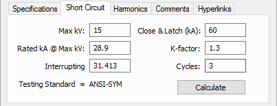
Figure 2: Short Circuit Tab (ANSI)
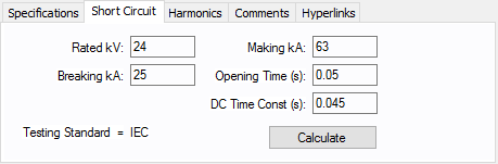
Figure 3: Short Circuit Tab (IEC)
|
ANSI
|
| Option |
Description |
| Max kV |
Maximum voltage for which the breaker is designed and the upper limit for operation. |
| Rated kA @ Max kV |
Rated interrupting kA of the breaker at the breaker’s maximum voltage. |
| Interrupting (kA) |
Interrupting rating of the breaker. |
| Close & Latch (kA) |
Close & latch rating of the breaker. |
| K-factor |
Ratio of rated maximum voltage to the lower limit of the range of operating voltage in which the required symmetrical and asymmetrical interrupting capabilities vary in inverse proportion to the operating voltage. |
| Cycles |
Interrupting time of the breaker in cycles. |
|
IEC
|
|
Rated kV
|
The rated voltage is equal to the maximum system voltage for which the equipment is designed.
|
|
Breaking kA
|
The breaking current is the highest short circuit current which the circuit breaker is capable of breaking.
|
|
Making kA
|
The making current is the highest prospective peak current which the circuit breaker is capable of making. It is 2.5 times (50 Hz) or 2.6 times (60 Hz) the value of the rated short circuit breaking current.
|
|
Opening Times (s)
|
Opening time of a circuit breaker defined according to the tripping method as stated below and with any time delay device forming an integral part of the circuit breaker adjusted to its minimum setting:
- For a circuit-breaker tripped by any form of auxiliary power, the opening time is the interval of time between the instant of energizing the opening release, the circuit-breaker being in the closed position, and the instant when the arcing contacts have separated in all poles.
- For a self-tripping circuit breaker, the opening time is the interval of time between the instant at which, the circuit-breaker being in the closed position, the current in the main circuit reaches the operating value of the overcurrent release, and the instant when the arcing contacts have separated in all poles.
|
|
DC Time Const (s)
|
The DC component of a short circuit decays exponentially with a time constant in seconds which depends on the frequency and X/R ratio.
|
|
Both
|
| Testing Standard |
The data in the library for the breaker is applicable for the specified test standard. The following testing standards are defined:
- ANSI-TOTAL: The interrupting and momentary close & latch ratings are both in asymmetrical kA (total rms kA). Circuit breakers prior to 1964 used this test standard.
- ANSI-SYM: The interrupting rating is in symmetrical kA whereas the momentary close & latch rating is in asymmetrical kA (total rms kA).
- ANSI-Crest: The interrupting rating is in symmetrical kA whereas the momentary close & latch rating is in peak kA.
- IEC: The circuit breaker ratings are as per IEC test standard.
|
| Calculate |
Fills in computed values based on the device library entry for Mfr, Type, Style and the base kV. You can override these values by typing in different numbers.
|
Harmonics Tab
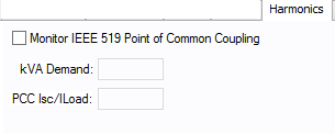
Figure 4: Harmonics Tab
| Option |
Description |
| Monitor IEEE 519 Point of Common Coupling |
EasyPower can monitor whether or not the IEEE 519 guideline for harmonics is met at the point of common coupling.
If selected, then the Harmonics Report indicates when this guideline is not being met.
|
| kVA Demand |
The kVA demand. |
| PCC Isc/Load |
The ratio of short circuit current to load current at the point of common coupling. |
Other Tabs
See Common Tabs for information on the Location, Reliability, Comments, Hyperlinks, Media Gallery, or Collected Data tabs.
More Information