Coordination Options
You can specify some features of TCC appearance using Coordination Options. When you are in Coordination focus, click  PDC Options (Coordination Options) to open the dialog box.
Note: The Coordination Options are not available when the TCC plot window is open.
General
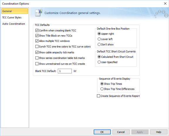
Figure 1: Coordination Options Dialog Box
TCC Defaults
Select the check boxes to control the TCC options.
|
Option |
Description |
|---|---|
|
Confirm when creating blank TCC |
When you plot a TCC without selecting any equipment, a blank TCC is created. This check box controls whether a message is displayed when a blank TCC is being created. |
|
Show Title Block on new TCCs |
Show or hide the TCC title block while creating a new TCC. After the TCC is created, you can select to show or hide the title block using the |
|
Enable multiple TCC windows |
When this option is selected, you can create multiple TCC windows. When this option is not selected, creating a new TCC closes the previously opened TCC window. Before closing the previously open TCC, you are asked if you want to store the TCC. |
|
Synch TCC one-line colors to TCC curve colors |
When this option is selected, the protective device symbols on the one-line window have the same color as the corresponding curves in the TCC window. |
|
Show cable ampacity tick marks |
When this option is selected, a tick mark is placed at the top of the TCC to indicate the ampacity of the cable. |
|
Show series coordination table tick marks |
When this option is selected, a tick mark is placed on the TCC at the amp value up to which a pair of protective devices (typically LV breakers) are selectively coordinated as per tables published by manufacturers. |
|
Show unrestrained curves on TCC create |
When this option is selected, TCC curves plot unrestrained ZSI curves. The ZSI state reflects these settings when a subsequent fault is performed. When it is not selected (which is the default setting), the initial TCC plot shows the restrained delay for short time and ground. After you fault a single bus, it simulates an unrestrained delay for the most downstream breaker, and a restrained delay for the upstream breakers. |
|
Blank TCC Settings |
Sets the default base voltage for calculating current on the new blank TCC. |
|
Default One-line Box Position |
Sets the location of the one-line box on the lower left or upper right corner of the TCC plot area when making a new TCC plot. |
|
: The short circuit currents used in the TCC can be calculated from short circuit or user-specified.
|
|
|
Select to either show the absolute trip times or the trip time difference from the next downstream device for a faulted bus on the one-line. (ANSI only.) |
|
|
When selected, this creates the Sequence of Events report when a bus is faulted in the Coordination focus. (ANSI only.) |

TCC Curve Styles
You can change the default format (color, lines, weight) of the curves that are plotted for various devices. To change the default color of any device, select that device in the Curve window of the dialog, and select Change for the order of the curve. The order of the curve, 1, 2, 3, etc., is the first, second, third, etc. curve plotted for the same type of device.
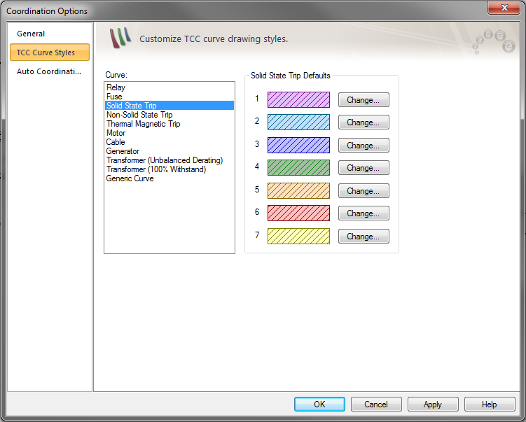
Figure 2: TCC Curves Style Tab of Coordination Options
Auto Coordination (ANSI Only)
The Auto Coordination options are described in Auto Coordination Options. This option is available if you have the SmartPDC™ (auto-coordination) feature.
More Information
| Coordination with PowerProtector™ | |
| Auto Coordination Options |