Zone Selective Interlock (ZSI)
You can model ZSI for low voltage breakers. The library has data in the Solid State Trip section for ZSI of some LV breakers. To model the ZSI settings of any breaker, the data must be defined in the library. The settings on the breaker may depend on the design of the breaker. EasyPower models ST ZSI, Ground ZSI and Self Restrained breakers. Select the appropriate check boxes in the ZSI tab of the LV Breaker Data dialog. When the In and Out terminals for ZSI are jumpered, the breaker is Self Restrained.
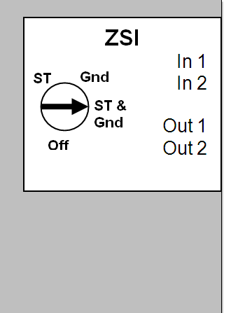
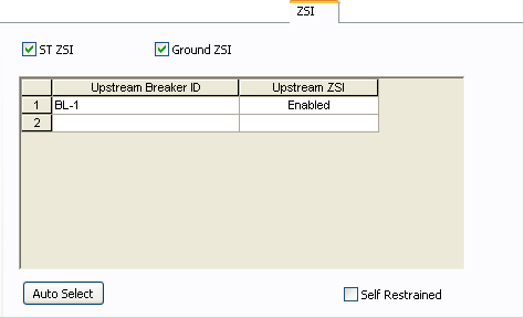
Figure 1: Typical ZSI Settings on Breakers
The sample one-line below shows the trip zones for various circuit breakers. The breaker in Zone 3 in this example is the furthest downstream. In the ZSI tab of the breaker’s dialog, the breaker in Zone 2 needs to entered as the Upstream Breaker. Similarly, the breaker in Zone 1 needs to be entered as the Upstream Breaker for Zone 2 breaker.
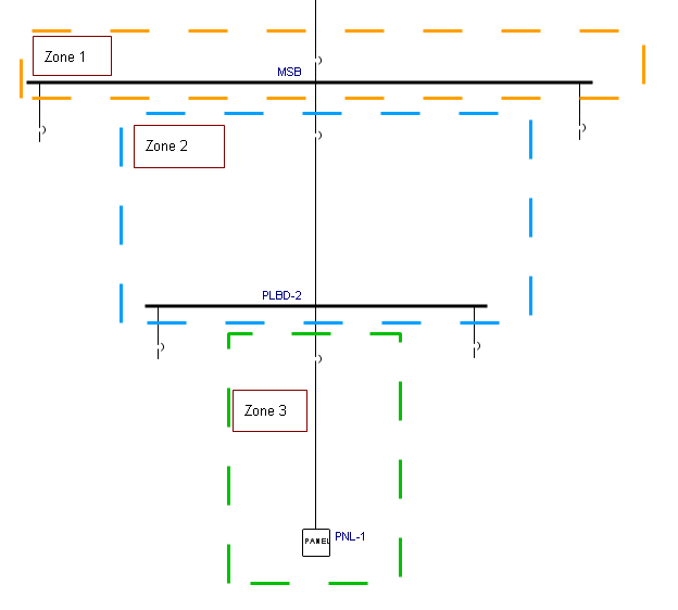
Figure 2: Trip Zones
Note: Before filling out the ZSI data in the LV Breaker Data dialog boxes, make sure that the other settings in the Solid State Trip have been filled out for all upstream breakers.
TCC Plots for ZSI Breakers
When you plot TCC for breakers with ZSI tripping, the initial plot shows the restrained trip times. This enables viewing whether the breakers are selectively coordinated during restrained mode. This is a requirement for ZSI tripping to be effective in selective coordination. After the TCC is plotted, you can then fault buses on the one-line, one at a time. EasyPower detects the fault zone and shows the unrestrained trip for the breaker in the zone.
More Information
| Coordination with PowerProtector™ |