Specifying Arc Flash Hazard Data for Equipment
You can specify the arc flash hazard data for any equipment by storing the data in an associated bus. The bus may represent the terminals or conductors. Equipment such as MCCs and panels are also modeled similar to buses and they store data for arc flash hazard.
Here, we will demonstrate how to specify arc flash hazard data for a bus. To open the Bus Data dialog box, on the Home tab, click  Database Edit, and then double-click on the bus.
Specifying Equipment Type
In the Specifications tab of the dialog box, the Type field describes the type of enclosure and is used for arc flash calculations. The equation or parameters for evaluating the incident energy and flash protection boundary differ depending on the enclosure type.
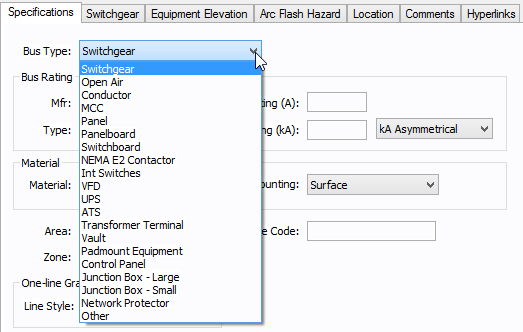
Figure 1: Specifying Equipment Type for Arc Flash Hazard
Specifying Arcing Time
You can specify the arcing time and other arc flash settings on the Arc Flash Hazard tab.
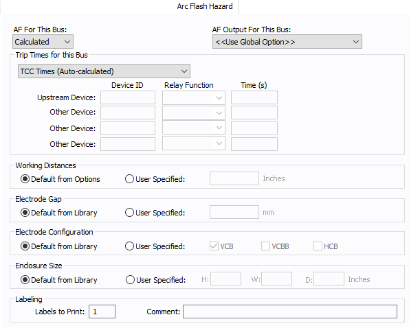
Figure 2: Bus Data-Arc Flash Hazard Dialog Box
You can specify how you would like arc flash results determined for this bus using AF for this Bus.
Calculated: When the bus is faulted, EasyPower the performs arc flash hazard analysis using the calculation method specified in Short Circuit Options. EasyPower uses other settings on this tab as part of the calculations.
Excluded: Select to exclude the bus from arc flash reports. An example of when you might select this option is for a bus that is required to model the electrical parameters of the system but does not actually represent a piece of electrical equipment. Other applications include nodes and tap-offs (junctions), where energized work is not required.
Forced To: When you select this option, you can enter the incident energy and arc flash boundary for this bus. The incident energy and arc flash boundary values are shown on the one-line and in reports and work permits. This can be used for instances where you need to apply a calculation that is outside the scope of the industry standard calculations.
Specifying Arc Flash Output
You can specify whether to display results on the line side or the load side of the Main protective device of the bus equipment. If the arc flash hazards output for this bus needs to be different from the global option, use this field. The choices are:
- <<Use Global Option>>: Use the option specified in Short Circuit Options.
- Including Main: Always display the arc flash hazard results on the load side of the Main protective device for this bus equipment regardless of what options are selected in the Short Circuit Options.
- Excluding Main: Always display the arc flash hazard results on the line side of the Main protective device for this bus equipment regardless of what options are selected in the Short Circuit Options.
- Both (Incl & Excl Main): Always display the arc flash hazard results on both the line side and the load side of the Main protective device for this bus equipment regardless of what options are selected in the Short Circuit Options.
Specifying Trip Times
You can select the method for determining trip times for this bus by choosing from the following:
- Pre-defined Fixed Times: Obtains arc clearing time for the bus from the library default values. This is not the same as the trip times calculated form the TCC curves of the upstream trip device. The values stored in the library are simply predefined approximate trip times. This is a legacy method and is not recommended.
- User-defined Times: With this option you can specify the protective device clearing time for each bus. The details of arcing time for the bus can be specified in the fields Device ID, Relay Function and Time (s). When this option is selected, a time must be specified.
- TCC Times (Automatically Calculated): Arc flash incident energy are calculated based on time characteristic current curves specified in each protective device data dialog box. The trip clearing time of the equipment where the device is a relay controlled breaker is the sum of the breaker mechanism opening time (for example, 3, 5, or 8 cycle), the relay trip time, and any time entered into the Relay Data, System, and Aux Time data fields.
- User-defined and TCC Times: Provides results for both user-defined times and TCC times as described above.
- User-defined One-line Device: With this option, you can specify which device you want to use for the TCC time, and the program will obtain the trip time automatically. You can select a device type (relay fuse, or low voltage breaker) and device ID. If you select a relay, you also select the relay function.
Note: When a user-defined time is specified and the calculation method is set to use the integrated method, only the upstream device setting is used. The time is considered as the maximum length of the simulation. See The Integrated Method for more information.
Specifying Working Distance
You can specify the working distances shown on the one-line and in reports and work permits.
- Default from Options: When selected, the program uses the workings distances from the Default Working Distances spreadsheet in the Arc Flash Hazard Options.
- User Specified: Selecting this option enables you to enter the working distance for this item.
The units displayed are based on the units selected in Arc Flash Hazard Options on the System tab. For inches, the range is 1-1000. For meters, the range is 0.1 to 1000.
Specifying Electrode Gap
You can specify the electrode gap shown on the one-line and in reports and work permits.
- Default from Library: When selected, the program uses the electrode gap from the device library.
- User Specified: Selecting this option enables you to enter the electrode gap for this item. The range is between 0.1 and 25,000 mm.
Specifying Electrode Configuration
You can specify the electrode configuration shown on the one-line and in reports and work permits.
- Default from Library: When selected, the program uses the electrode configuration from the device library.
- User Specified: Selecting this option enables you to select the electrode configuration for this item. The options available are based on the orientation of the electrodes, whether they are inside an enclosure, and in one instance, whether they terminate into a barrier.
- VCB: Vertical electrodes inside an enclosure.
- VCBB: Vertical electrodes terminating in an insulating barrier inside an enclosure.
- HCB: Horizontal electrodes inside an enclosure.
- VOA: Vertical electrodes in open air.
- HOA: Horizontal electrodes in open air.
Electrodes in Enclosures:
Electrodes in Open Air:
You can select more than one configuration to represent the multiple types of conditions that can occur for the equipment. EasyPower evaluates each configuration and then provides values for the highest incident energy based on the existing electrode configurations. Annex C in the IEEE 1584-2018 standard describes examples where you might use more than one electrode configuration.
Tip: To change the electrode configuration for multiple items on the one-line, select the items in the Database Edit focus and then on the Home tab, click Change > AF Bus Electrode Configuration.
Electrode configurations are only applicable to the IEEE 1584-2018 standard. For more information, see Electrode Configuration.
Specifying Enclosure Size
You can specify the enclosure size shown on the one-line and in reports and work permits.
- Default from Library: When selected, the program uses the enclosure size from the device library. The library provides typical values based on the equipment type and voltage.
- User Specified: Selecting this option enables you to enter the enclosure size for the item. This enables you to get more accurate calculation results, assuming the correct dimensions are entered.
The units displayed are based on the units selected in Arc Flash Hazard Options on the System tab. For inches, the range is .01-1000. For millimeters, the range is 0.1 to 25,000.
The enclosure dimensions affect arc flash.
- Arc flash is greatest for a 20 in. x 20 in. x 20 in. enclosure.
- Arc flash decreases as the height or width dimensions increase.
- In low voltage equipment with a height and width of less than 20 inches, arc flash decreases if the depth dimension is less than or equal to 8 inches.
Setting Label Options
Enter the number of labels you want to print for arc flash hazard analysis. If you enter "0," no labels will print.
You can type a comment that appears on the arc flash label when it is printed. For example, you could type a location description for the equipment to assist with label placement.
More Information
| Arc Flash Hazard Analysis |