Plotting User Selected Values – Define Plot
When you perform a simulation by double-clicking on the one-line, data is plotted in the AutoPlot tab. Based on the type of simulation, EasyPower selects the values to display in the AutoPlot. For example, if you double-click on an open motor breaker or switch to start a motor, the plot is provided with motor per-unit values for voltage, current, speed and torque. To see values elsewhere in your system, you need to define plots. Nine plots are available with up to a maximum of 5 curves per plot.

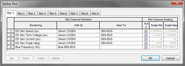
Figure 1: Define Plot dialog
To define a plot, on the Stability tab, click  Define Plots. In the Define Plot dialog box, select the values to plot by choosing the desired fields for Monitoring, With ID and Next To.
- Monitoring: Variable to be plotted. Example: voltage, current, power, torque, and so on.
- With ID: ID name of the equipment for which the variable is to be plotted.
- Next To: ID name of the bus to which the equipment is connected.
You can also select values by first selecting on an open Monitoring cell, and then right-clicking the desired equipment on the one-line, and selecting the desired value type to be plotted with the Define Plots dialog box open. The entire row is automatically populated.

Figure 2: Define Plot Using One-line Selection
The following values are able to be plotted in a dynamic simulation, if the appropriate equipment is being modeled and is in existence and enabled.
|
Value |
Units |
Comment |
|---|---|---|
| Bus | ||
|
Voltage |
pu |
|
|
Voltage |
kV |
|
|
Fault I |
pu |
|
|
Fault I |
Amps |
|
|
Angle |
Degrees |
|
|
Frequency |
pu |
|
|
Frequency |
Hz |
|
|
AF Energy |
Cal/cm/cm |
If AF Fault Enabled |
|
Network Dev |
||
|
Current |
pu |
See Note 1 |
|
Current |
Amps |
See Note 1 |
|
kW |
kW |
See Note 1 |
|
kVar |
kVar |
See Note 1 |
|
DS Motor |
||
|
Term Voltage |
pu |
|
|
Current |
pu |
|
|
Current |
Amps |
|
|
Speed |
pu |
|
|
Speed |
RPM |
|
|
Torque |
pu |
|
|
Load Torque |
pu |
|
|
Watts |
pu |
|
|
Vars |
pu |
|
|
kW |
kW |
|
|
kVar |
kVar |
|
|
Angle |
deg |
Sync Motor Only |
|
Field Voltage |
pu |
Sync Motor Only |
|
Power Angle |
deg |
Sync Motor Only |
|
D-Axis Current |
pu |
Sync Motor Only |
|
Q-Axis Current |
pu |
Sync Motor Only |
|
Psi''d |
pu |
Sync Motor Only |
|
Psi''q |
pu |
Sync Motor Only |
|
DS Gen |
||
|
Current |
pu |
|
|
Current |
Amps |
|
|
Speed |
pu |
|
|
Speed |
RPM |
|
|
Torque |
pu |
|
|
P Mechanical |
pu |
|
|
Watts |
pu |
|
|
Vars |
pu |
|
|
kW |
kW |
|
|
kVar |
kVar |
|
|
Field Voltage |
pu |
|
|
Angle |
deg |
Machine Angle |
|
Term Voltage |
pu |
|
|
Power Angle |
deg |
|
|
D-Axis Current |
pu |
Id |
|
Q-Axis Current |
pu |
Iq |
|
Psi''d |
pu |
Flux ψ’’d |
|
Psi''q |
pu |
Flux ψ’’q |
|
VPSS |
pu |
PSS Output Voltage |
|
AVR Out |
pu |
|
Network Dev values are those that have no Dynamic Stability Model defined, and include:
|
|
* For non-DS motors and generators, we mean that no model is defined in the Stability tab of the motor or generator data dialog, or their Enable check box is not selected.
More Information
| Dynamic Stability |
