Governor Models
Gas Turbine Governor
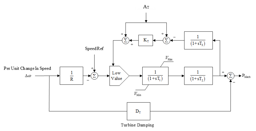
Figure 1: Gas Turbine Governor Model Block Diagram
|
Parameter |
Units |
Description |
|---|---|---|
|
R |
pu |
Droop |
|
T1 |
Seconds |
Governor control time constant |
|
T2 |
Seconds |
Combustion chamber time constant |
|
T3 |
Seconds |
Exhaust temp measurement time constant |
|
AT |
pu |
Ambient temperature load limit |
|
KT |
pu |
Load limit gain |
|
VMax |
pu |
Governor control max |
|
VMin |
pu |
Governor control min |
|
DT |
pu |
Damping |
Woodward Diesel Governor
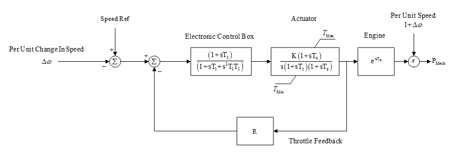
Figure 2: Woodward Diesel Governor Model Block Diagram
|
Parameter |
Units |
Description |
|---|---|---|
|
R |
pu |
Throttle feedback gain (affects droop) |
|
T1 |
Seconds |
Control box time constant |
|
T2 |
Seconds |
Control box time constant |
|
T3 |
Seconds |
Control box time constant |
|
T4 |
Seconds |
Actuator time constant |
|
T5 |
Seconds |
Actuator time constant |
|
T6 |
Seconds |
Actuator time constant |
|
TD |
Seconds |
Engine firing delay time |
|
K |
pu |
Actuator gain |
|
TMax |
pu |
Max actuator torque |
|
TMin |
pu |
Min actuator torque |
|
Droop / Isoch |
|
Switch (droop mode or isochronous mode) |
Woodward Steam PID1 Governor
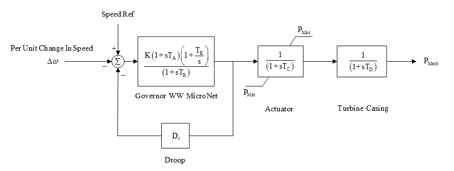
Figure 3: Woodward Steam PID 1 Governor Model Block Diagram
|
Parameter |
Units |
Description |
|---|---|---|
|
TA |
Seconds |
Governor control time constant |
|
TB |
Seconds |
Governor control time constant |
|
TE |
Seconds |
Governor control time constant |
|
TC |
Seconds |
Actuator time constant |
|
TD |
Seconds |
Turbine time constant |
|
K |
pu |
Governor control gain |
|
PMax |
pu |
Max power output |
|
PMin |
pu |
Min power output |
|
Dr |
pu |
Droop |
More Information
| Dynamic Stability | |
| Stability Data Parameters |