Motor Models
Double Cage Flux Induction Motor
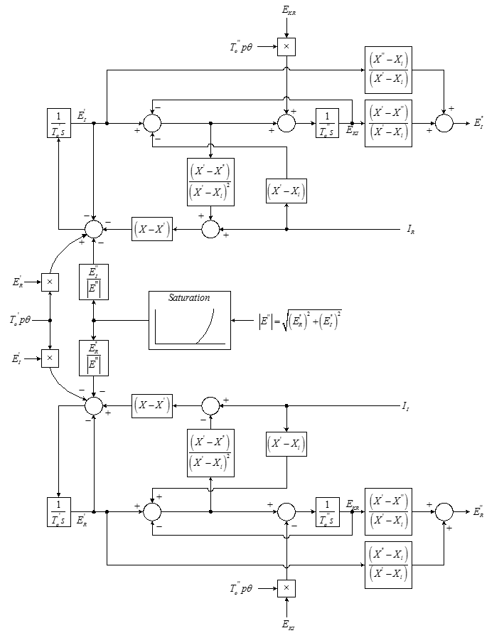
Figure 1: Double Cage Induction Motor Flux Model
|
Parameter |
Units |
Description |
|---|---|---|
|
Rated HP |
HP |
|
|
Rated Eff |
Percent |
|
|
Rated Speed |
RPM |
|
|
Rated Voltage |
Volts LL |
|
|
Rated Current |
Amps |
|
|
Rated PF |
|
|
|
Rated Slip |
pu |
Rated slip |
|
Start Trq |
pu |
Starting torque |
|
Start Crt |
pu |
Starting current |
|
Start PF |
|
Starting power factor |
|
Pull-Out Trq |
pu |
Rated pull-out torque |
|
Ra |
pu |
Stator winding resistance (armature resistance) |
|
Xl |
pu |
Stator leakage reactance |
|
X |
pu |
Unsaturated synchronous reactance |
|
X’ |
pu |
Unsaturated transient reactance |
|
X’’ |
pu |
Unsaturated sub-transient reactance |
|
T’o |
Seconds |
Transient OC time constant |
|
T’’o |
Seconds |
Sub-transient OC time constant |
|
E1 |
pu |
First voltage to define saturation |
|
E2 |
pu |
Second voltage to define saturation |
|
S( E1 ) |
pu |
Saturation at E1 |
|
S( E2 ) |
pu |
Saturation at E2 |
|
H |
kW-Sec / kVA |
Combined machine and load inertia |
|
Ld Tran Str |
Seconds |
Time at which load transfers – starting to running |
|
Ld Tran Rmp |
Seconds |
Time it takes to transfer load – starting to running |
|
SoftSt V1 (%) |
Percent |
Initial terminal voltage upon starting motor |
|
SoftSt V2 (%) |
Percent |
Intermediate voltage for motor start after T12 seconds. This defines the first slope of ramp. |
|
SoftSt V3 (%) |
Percent |
Final voltage for motor start at end of ramp after T23 seconds. This defines the final slope of ramp. |
|
SoftSt T12 (sec) |
seconds |
Time elapsed between V1 and V2 |
|
SoftSt T23 (sec) |
seconds |
Time elapsed between V2 and V3 |
Note: OC = Open Circuit
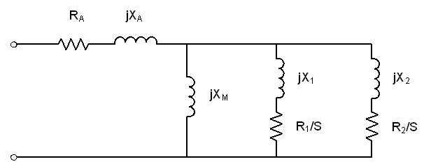
Figure 2: Double Cage Induction Motor Impedance Model – Type 1 Form
Synchronous Motor
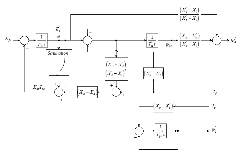
Figure 3: Synchronous Motor Model Block Diagram
|
Parameter |
Units |
Description |
|---|---|---|
|
Rated HP |
HP |
|
|
Rated Eff |
Percent |
|
|
Rated Speed |
RPM |
|
|
Rated Voltage |
Volts LL |
|
|
Rated Current |
Amps |
|
|
Rated PF |
|
|
|
Ra |
pu |
Stator winding resistance (armature resistance) |
|
Xl |
pu |
Stator leakage reactance |
|
Xd |
pu |
d-axis unsaturated synchronous reactance |
|
Xq |
pu |
q-axis unsaturated synchronous reactance |
|
X’d |
pu |
d-axis unsaturated transient reactance |
|
X’’d = X’’q |
pu |
d & q-axis unsaturated sub-transient reactance |
|
T’do |
Seconds |
d-axis transient OC time constant |
|
T’’do |
Seconds |
d-axis sub-transient OC time constant |
|
T’’qo |
Seconds |
q-axis sub-transient OC time constant |
|
E1 |
pu |
First voltage to define saturation |
|
E2 |
pu |
Second voltage to define saturation |
|
S( E1 ) |
pu |
Saturation at E1 |
|
S( E2 ) |
pu |
Saturation at E2 |
|
H |
kW-Sec / kVA |
Combined machine and load inertia |
|
Ld Tran Str |
Seconds |
Time at which load transfers – starting to running |
|
Ld Tran Rmp |
Seconds |
Time it takes to transfer load – starting to running |
|
EFD App Speed |
Percent |
Speed at which the field is applied during starting |
|
EFD App Value |
Percent |
Value of field voltage to apply during starting |
|
Rev Pwr Del |
Seconds |
Time it takes to trip the reverse power detection |
|
SoftSt V1 (%) |
Percent |
Initial terminal voltage upon starting motor |
|
SoftSt V2 (%) |
Percent |
Intermediate voltage for motor start after T12 seconds. This defines the first slope of ramp. |
|
SoftSt V3 (%) |
Percent |
Final voltage for motor start at end of ramp after T23 seconds. This defines the final slope of ramp. |
|
SoftSt T12 (sec) |
seconds |
Time elapsed between V1 and V2 |
|
SoftSt T23 (sec) |
seconds |
Time elapsed between V2 and V3 |
More Information
| Dynamic Stability | |
| Stability Data Parameters |