To set the short circuit control options, in the Short Circuit focus, click SC Options (toolbar menu: Tools > Short Circuit Options). On the Control tab, specify the options you want for controlling the behavior of a short circuit study.
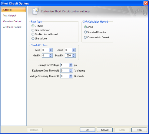
Figure 1: Control Tab of the Short Circuit Options Dialog Box
Fault Type: Four different types of faults are available during a short circuit analysis. The default is 3 Phase which is generally used to determine the highest available currents for equipment duty comparisons, and relaying. The other types, Line to Ground, Double Line to Ground, and Line to Line are generally used for specialized relaying applications or system troubleshooting.
X/R Calculation Type: Short circuit calculations are based on one of three methods:
IDC = Ö2 IAC RMS SYM exp (-p /|X/R|)
After each DC component is determined and totaled, the equivalent X/R ratio is found from the equation below.
Equivalent X/R = -p/ ln (S IDC / S IAC RMS SYM / Ö2)
The CCM method provides a conservative approach to obtain the fault point X/R ratio and appears to do the best overall job without being over-conservative.
Reference: Parise G., A new approach to calculate the decaying AC contributions to short-circuit: the ‘characteristic’ currents method; IEEE Transactions on Industry Applications, Vol. 31, No. 1, January/February 1995.
"Fault All" Filters: Enables you to specify a specific bus Area, Zone, and kV Range that to fault and report when you fault multiple or all buses. This type of analysis is useful when you are interested in studying only a specific region and do not need all of the output associated with a full system analysis. This method is common for old-style text programs. In EasyPower, it is just as simple to select the buses you wish to fault from the one-line fault buses. Only the selected buses are faulted.
Driving Point kV PU: System fault point voltage in per-unit. This value defaults to 1.0 per-unit.
Equipment Duty Threshold: Sets the lower limit for flagging breaker violations in SmartDuty™. If the threshold is set to -10 percent, SmartDuty™ will flag all equipment which has short circuit duties within 10 percent of their maximum rating (greater than 90% of their rating).
Note: The ability to automatically check equipment duties during analysis is only available if you have purchased the SmartDuty™ option to EasyPower.
For example, a GE AM-13.8-500 air blast breaker has a momentary and interrupting duty rating of 19.56/37 kA at 13.8 kV. SmartDuty™ provides a warning flag if the current exceeds 17.6/33.3 kA in either the momentary or interrupting rating. If the current exceeds 19.56/37 kA, a violation is flagged.
Note: You must click  Equipment Duty from the Short Circuit focus (toolbar menu: View > Equipment Duty) for this field to have any effect on the one-line result output.
For this field to have any effect for text result output, you must select the Equipment Duty check box in the Text Output tab of the Short Circuit Options dialog box.
Voltage Sensitivity Threshold: Sets the lower limit setting for flagging voltage violations. If the threshold is set to -30 percent, bus voltages lower than 30 percent (70 percent voltage) of the bus' base kV is flagged. This enables you to quickly check for motor contactor dropout, lighting flicker, and so on.
Note: For this field to have any effect, you must select one or more of the Voltage Sensitivity check boxes in the One-line Output or the Text Output tab of the Short Circuit Options dialog box.
To set the short circuit one-line output options, in the Short Circuit focus, click SC Options (toolbar menu: Tools > Short Circuit Options). On the One-line Output tab, specify the options you want for controlling what is output to the one-line during the short circuit study.
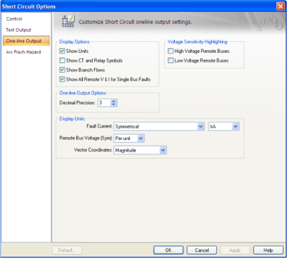
Figure 2: One-line Output tab of Short Circuit Options Dialog Box
Display Options: Enables you to control what appears on the one-line while performing short circuit calculations. You can select or remove the following outputs.
Decimal Precision: This sets the number of digits past the decimal point for values displayed on the one-line.
Fault Current: Enables you to choose the unit of fault current and the type of current. You can display the following types of currents on the one-line:
Iasym = I sym [1 + 2e{-4πÁ / (X/R)}] 1/2
Á= 0.49 - 0.1 e{-(X/R)/3}
For interrupting duty currents the asymmetrical value is based on the fault point X/R ratio, the No AC Decay (NACD) ratio, the contact parting time of the breaker, and whether the breaker is rated on a Total or Symmetrical basis. The NACD ratio consists of two factors dependent upon whether generation is Local or Remote. The equations and calculation procedures are too detailed for this discussion. For more information, see Reference1AC High Voltage Circuit Breakers Rated on a Symmetrical Current Basis, ANSI/IEEE Std. C37.010-1979..
For 30 cycle faults no asymmetry is present, and the asymmetrical current equals the symmetrical current.
Max Symmetrical and (Max Asymmetrical): This choice displays both symmetrical and asymmetrical branch flows.
The following fault current units are available for display in the one-line:
Remote Bus Voltage (Sym): Voltages can be displayed as symmetrical voltage in either physical units (kV) or in per-unit values.
Voltage Sensitivity: This option highlights all buses on the one-line with voltages below a user-specified threshold value for a single fault. Voltage sensitivity studies are used to determine problem areas which may cause contactor dropout or equipment failure for critical areas such as boiler feed water pumps, ID fans or drive systems. Refer to the Control tab of the Short Circuit Options dialog box for setting the threshold value.
Both high and low voltage remote buses can be studied.
To set the short circuit text output options, in the Short Circuit focus, click SC Options (toolbar menu: Tools > Short Circuit Options). On the Text Output tab, specify the reports required for your short circuit study. Text results are displayed in individual result windows which can be scrolled, reviewed, and printed at your discretion. Because of the many text output combinations, details of each option are described in general terms. You are encouraged to try different options and levels of detail for your particular study requirements.
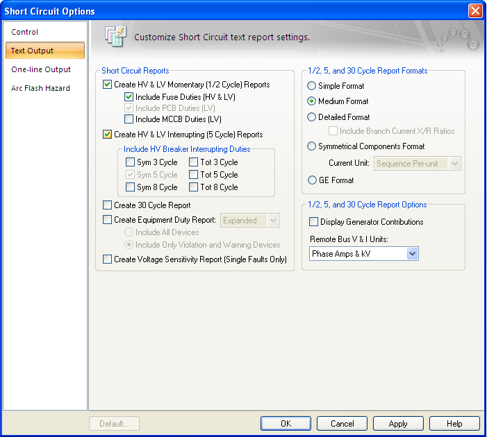
Figure 3: Short Circuit Options—Text Output Tab
Short Circuit Reports: Five different text reports are available during short circuit analysis: Momentary, Interrupting, 30 cycle, Equipment Duty, and Voltage Sensitivity. You can view the results onscreen or print them. EasyPower can display multiple result windows at one time and you can study them using the Window > Tile features.
Note: The ability to automatically check equipment duties during analysis is only available if you have purchased the SmartDuty™ option to EasyPower.
Text output to the result windows are independent of one-line output.
For example, you might want to study detailed text results of momentary and 30 cycle currents while displaying equipment duty results on the one-line. To do this, select the Momentary and 30 cycle check boxes in the Text Output tab of the Short Circuit Options dialog box. Click  Equipment Duty (toolbar menu: View > Equipment Duty). When a fault operation is done, EasyPower automatically applies the necessary faults for duty analysis and displays the results on the one-line. In addition, the momentary and 30 cycle faults are performed and displayed in the text result windows.
Note: The voltage sensitivity operation only tabulates momentary text results, regardless of what you might have chosen for the one-line's voltage sensitivity display.
Include Fuse Duties (HV & LV): The fuse interrupting currents are displayed in the High and Low Voltage Momentary result window since fuses open under momentary currents.
Fuse multiplying factors are based on the fault point X/R ratio and the fuse test X/R ratio. The interrupting currents are calculated by adjusting the symmetrical current if the equipment test X/R is less than the fault point X/R ratio. The following equation is used to determine the currents:
Iadjsym =Isym [1 + 2e{-4πÁsys /(X/Rsys)}]1/2 / [1 + 2e{-4πÁsys /(X/RTest)}]1/2
Á= 0.49 - 0.1 e-(X/R)/3}
Standard test X/R ratios are 5, 8, 12, and 15 for distribution and power fuses2IEEE Standard Design Tests for High Voltage Fuses, Distribution Enclosed Single Pole Air Switches, Fuse Disconnecting Switches, and Accessories, C37.41-1988..
Include HV Breaker Interrupting Duties: This option lets you display ANSI standard interrupting duty currents for high voltage breakers. The breaker interrupting results are displayed in the High Voltage Interrupting result window according to the interrupting time chosen under the Cycles option (3, 5, & 8 cycles).
The interrupting currents are calculated by adjusting the symmetrical current by a multiplying factor. For breakers, the multiplying factor is based on the fault point X/R ratio, the No AC Decay (NACD) ratio, the contact parting time of the breaker, and whether the breaker is rated on a Total or Symmetrical basis. The NACD ratio consists of two factors dependent upon whether generation is Local or Remote. The equations and calculation procedures are too detailed for this discussion. If additional information is required refer to Reference3Sample System for Three Phase Short Circuit Calculations, Conrad St Pierre, IEEE/IAS Mar/Apr 1990.,4Interpretation of New American National Standards For Power Circuit Breaker Applications, Walter C. Huening Jr., IEEE/IAS Sept/Oct 1969.,5AC High Voltage Circuit Breakers Rated on a Symmetrical Current Basis, ANSI/IEEE Std. C37.010-1979..
Include LV Breaker Duties: This option displays low voltage power circuit breaker (LVPCB) and molded case circuit breaker (MCCB) interrupting currents for low voltage momentary faults. The results are displayed in the Low Voltage Momentary result window. Notice that under ANSI terminology, when the term interrupting is used for low voltage equipment, it applies to momentary or 1/2 cycle faults. This is because low voltage equipment typically interrupts within 1/2 cycle of fault inception.
The interrupting currents are calculated by adjusting the symmetrical current if the equipment test X/R is less than the fault point X/R ratio6Low Voltage Power Circuit Breakers Used in Enclosures, ANSI/IEEE Std. C37.13-1981.,7Low Voltage Power Circuit Breakers, NEMA Publications BU-195x, and BU1-1972.. The following equation is used to determine the currents:
Iadjsym = Isym [1 + e{-2πÁ/(X/Rsys)} ] / [1 + e{-2πÁ/(X/RTest)} ]
Á= 0.49 - 0.1 e{-(X/R)/3}
X/Rtest = TAN[ARCCOS(Tested PF)]
Create Equipment Duty Report: Creates a report with current flows through every breaker and evaluates the fault currents (breaker duty) in percentage of breaker rating.
Create Voltage Sensitivity Reports: Creates reports listing all buses which have voltages below a specified threshold when a fault occurs in the system.
1/2, 5 and 30 Cycle Report Formats: Three types of text output styles are available, ANSI, Symmetrical Components, and GE. The ANSI style is designed for reporting all the significant ANSI Standard breaker comparison multipliers and results for standard protective relaying requirements. If you select the ANSI output style, three different output formats are available. Levels 1-3 provide the standard format designed for equipment duty comparison and relaying currents. Level 3 contains the most detailed information.
The symmetrical component style is designed specifically for specialized relaying purposes that require a component output for both voltages and current. You are encouraged to try different options and levels of details for your particular study requirements.
The other option is GE, which is the popular General Electric short circuit format.
Remote Bus V&I Units: These options let you display remote bus results in Sequence Per-unit, Phase Amps & kV, or Phase Per-unit format.
Branch X/R Ratios: Lets you display branch X/R ratios for each contributing branch current.
Display Generator Contributions: Displays generator and utility voltages and currents for each fault.
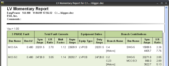
Figure 4: Sample Short Circuit Report
To select arc flash hazard options, click  SC Options from the ribbon and select the Arc Flash Hazard tab.
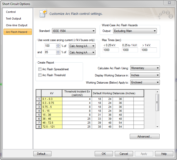
Figure 5: Short Circuit Options – Arc Flash Hazard tab
Standard: You can select any of the following standards for calculation method.
The IEEE 1584 equations are applicable up to 15kV. Above 15kV, the program uses the Ralph Lee method, and the distance “X’ factor and the gap from the library do not apply. This method has the distance exponent of 2.
Worst-Case Arc Flash Hazards: EasyPower obtains the arcing time from the upstream protective device of the faulted bus. The program uses the coordination feature PowerProtector™ to calculate the trip time for the estimated fault current passing through the protective device. This is the most accurate method. This option works only if you have the PowerProtector™ feature included in your EasyPower.
Output: Select one of the options in the drop down box to evaluate the arc flash hazard results for any bus in the following ways:
Note: Panels typically have the main breaker, bus bar and feeder breakers housed inside the same enclosure. Opening the front cover would expose a worker to arc on the line side of the main breaker. To simulate this hazard, select the Excluding Main option, since the device to interrupt faults would have to be an upstream device.
Use the worst case arcing currents: IEEE 1584 recommends using two scenarios – one with 100% of estimated arc current and the other with 85% of estimated arc current. This is due to the fact that arc currents may be random and usually vary by some proportion about the estimated value. For inverse-time over-current characteristics of protective devices, the arcing time is greater for smaller currents than it is for larger currents. Since the incident energy of arc faults is more sensitive to arcing time than it is to arc currents, it is necessary to obtain a more accurate arcing time. IEEE 1584 proposes taking 85% of the initial estimate of the arc current.
EasyPower enables you to consider two scenarios of arc currents. EasyPower calculates both scenario and automatically reports the worst case of incident energy, thus providing conservative results.
The IEEE 1584 recommended 100% and 85% of arc current are default values. You may change these ratios by typing in the fields or using the buttons to increase or decrease the values.
When 100% or the upper value yields greater arc flash incident energy, then the text results are displayed in black in the Arc Flash Report spreadsheet. When 85% or the lower value yields greater incident energy, the text is displayed in pink.
Max Times (sec): The Max Time is the maximum time that the program uses to calculate the incident energy. If the trip time calculated as per device TCC is less than the specified maximum time, then the device trip time is used. If the device trip time exceeds the specified maximum time, then the Max Time value is used. The default maximum time is 1000 seconds.
Calculate Arc Flash Using: Specify the fault current used during arc flash calculations. Select between Momentary, Interrupting, and 30 Cycle fault currents or the Integrated method.
Display Working Distance in: You can select the units for working distance from any of the following. This affects the results such as arc flash boundary as well.
Working Distances (Below) Apply to: You can specify separate working distances for open air and enclosed space. Select the appropriate choice to view or edit the values in the spreadsheet. Typically for medium voltage, switches and fuses at open air may be operated from a greater distance.
Arc Flash Spreadsheet: Select this check box to obtain spreadsheet report of arc flash hazard calculations when faulting buses.
Show: Fault current displayed in arc flash hazard report.
Arc Flash Threshold: Check this box to obtain a report of buses that exceed the arc flash threshold incident energies specified in the options. You can specify any incident energy as the threshold for various voltage levels by typing in the values in the spreadsheet in the Arc Flash Hazard options. All equipment exceeding the hazard thresholds will be displayed in red on the one-line.
Threshold Incident energy: For every voltage level you can specify the threshold incident energy. Equipment with incident energies exceeding the threshold values will be highlighted in red in the one-line output and they will be reported in the Arc Flash Threshold Report. This provides instant notification of a danger condition. All equipment with incident energies exceeding the threshold values are displayed in red on the one-line.
Default Working Distances: For every voltage level, you can specify up to five working distances for which the incident energy will be provided in the Arc Flash Report. In the one-line output, results will be shown only for the shortest working distance, which has the highest incident energy.
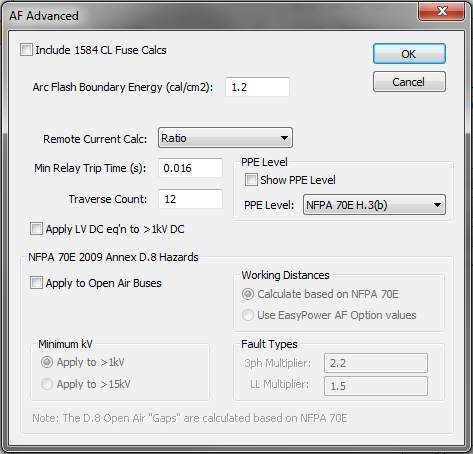
Figure 6: Advanced Arc Flash Options
Include 1584 CL Fuse Calcs: Use IEEE 1584 equations for current limiting fuses to determine incident energy. This method calculates the let through arc flash incident energy based on bolted fault currents and UL class of fuse. Equations are available for classes L and RK1. This is applicable only for low voltage systems. The fuse equations are effective only when the fault current is high compared to the minimum fault current required for current-limiting. When the fault current is well below the current-limiting range of the fuse, the standard arc flash equations are used. When the 1584 CL Fuse Calculations are used for any bus, the Arc Flash Hazard Report shows the bolted fault current but not the arc current and the trip times, since these values are not used to determine the incident energy.
Note: The IEEE 1584 CL fuse equations provide incident energy at 455mm. The default low voltage working distance in the program is 18 inches (which is equivalent to 457.2 mm). Therefore, the results for 18 inches will be slightly different from the results for 455mm.
Arc Flash Boundary Energy (cal/cm2): NFPA-70E specifies two types of arc flash boundaries. When the arcing time is less than 0.1 second, the boundary is at a distance at which the incident energy is less than or equal to 1.5 cal/cm2. When the arcing time is greater than 0.1 second, the boundary is at a distance at which the incident energy is less than or equal to 1.2 cal/cm2. These are the default values. You can change them if necessary.
Remote Current Calc: EasyPower supports two different methods for determining the remote current through protective devices during an arc fault:
Minimum Relay Trip Time: This is the minimum trip time used for relays. The default value is 0.016s. If the relay trip time in a TCC shows less than this specified value, this minimum time is used in arc flash. One-lines created in versions previous to 8.0.2.305 will show a minimum relay trip time of 0.01 seconds. You can change this option.
Traverse Count: This is the maximum number of buses the program will traverse upstream from the faulted bus to find the trip device. The default count is 12, to optimize for speed. You can increase the Traverse Count value if necessary. Examples of where it may be necessary to increase the Traverse Count include long distribution feeders with multiple taps, busways (bus ducts) with multiple bus plugs, underground distribution systems, and wind farms.
NFPA 70E 2009 Annex D.8 describes estimating the incident energy for overhead open air systems 1kV to 800kV. These calculations are based on open air phase-to-ground arcs.
Apply to Open Air Buses: Enables calculations for open air buses based on the Annex D.8 method.
Minimum kV:
Working Distances:
Fault Types: These are multipliers used to estimate the incident energies for 3-phase fault and line-to-line faults for arcs on open air buses.
| ANSI Short Circuit Reference | SmartDuty™ |
| Faulting a Bus | Controlling the Analysis |
| Voltage Sensitivity Studies | TCC Options |