 PDC Options and then select the Auto Coordination tab.
  SmartPDC and select Smart PDC Options.
Auto Coordination Options enable you to specify how your system will be coordinated. To select the auto coordination options:
PDC Options and then select the Auto Coordination tab. SmartPDC and select Smart PDC Options.
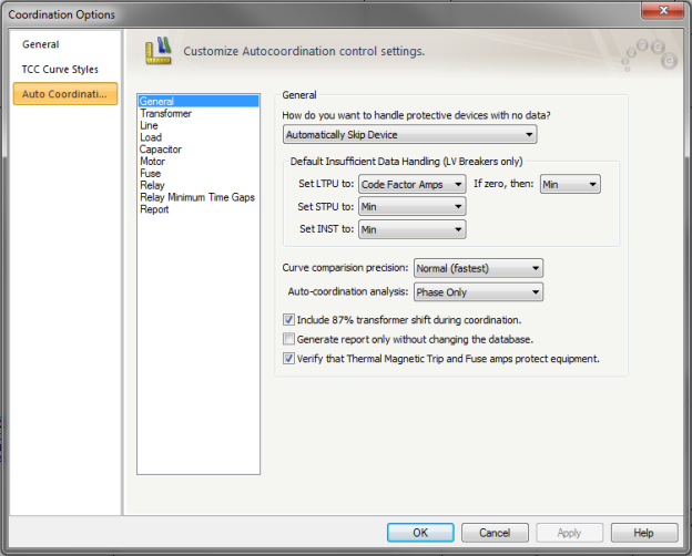
Figure 1: Coordination Options - General
How do you want to handle protective devices with no data?: Enables you to decide how to proceed when a protective device to be coordinate does not contain trip data. The choices are:
The trip settings are set as selected below, if the curve cannot be coordinated with other equipment because of insufficient data.
Set LTPU to: Select the type of load current calculation to use to set LTPU. The following choices are available:
If zero, then: If the selected load type amps are equal to zero, the LTPU is set as selected. The possible LTPU selections for this case are Min, Medium, and Max.
Set STPU to: Select the setting for STPU if coordinating equipment does not have sufficient data or coordinating equipment is not present. The possible STPU selections are Min, Medium, and Max.
Set INST to: Select the setting for INST if coordinating equipment do not have sufficient data or no coordinating equipment is present. The possible STPU selections are Min, Medium, and Max.
Curve comparison precision: Select the amount of precision used while coordinating between curves. Selecting a higher level of precision will enhance coordination. There are three levels of precision are shown below. The default level of precision is Normal (fastest).
The selected level of precision will affect the amount of time needed for EasyPower to auto coordinate each selected protective device.
Auto-coordination analysis: Select the analysis:
Include 87% transformer shift during coordination: The program will take into consideration the 87% factor while comparing primary currents with secondary in a wye-delta transformer with line-to-line fault on the delta side.
Generate report only without changing database: This enables you to view comments regarding auto coordination of equipment, without changing protective device settings in the temporary database. When the check box is not selected, the settings are changed temporarily in Coordination focus. These changes need to be stored to the database when returning to Database Edit focus if you want to save them.
Verify that Thermal Magnetic Trip and Fuse amps protect equipment: If this check box is selected, the program compares the trip amps of the breaker or fuse with the rated amps of the protected cable or transformer, and reports possible overload protection issues.
![]()
Figure 2: Auto Coordination Options - Transformer
NEC Requirements for Transformer Protection: The table is the NEC Table 450-3(A) for transformer primary over 600V. The table shows the maximum rating or setting of over current protection for transformers. You can change the values in the spreadsheet.
Verify FLA NEC limits with: When setting SST for transformer FLA, the LTPU is set based on the following selections:
Enable one setting past transformer FLA NEC limit for LTPU selection: Selecting the check box increases LTPU setting by one past the selected transformer FLA NEC limit. If the check box is not selected, LTPU is set as originally specified.
How should the LTPU selection of LV devices be prioritized?: LTPU coordination is selected by coordinating with other protective devices or with maximum transformer FLA.
Use closer selectivity with downstream protective devices: LTPU setting is set based on coordination with downstream protective devices.
Use Max transformer Amps: LTPU is set based on maximum transformer amps.
Minimum gap between inrush and relay: Sets the relay time delay at specified seconds higher than the transformer inrush time.
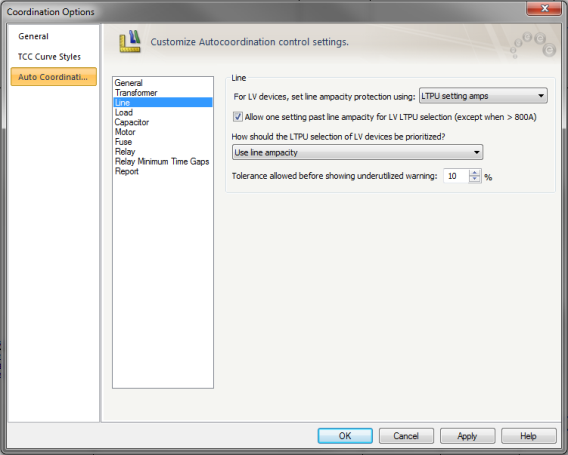
Figure 3: Auto Coordination Options- Line
For LV devices, set line ampacity protection using: Select the cable protection method from the following:
Allow one setting past line ampacity limit for LTPU selection: When the check box is selected, LTPU setting is set to the next setting past the cable ampacity. As per NEC, this is enabled only when the amp rating is 800A or less.
How should the LTPU selection of LV devices be prioritized?: Enables you to select the method for coordinating solid state trip and cable.
Tolerance allowed before showing underutilized warning: If the trip amps of the device is lower than the cable ampacity by the specify tolerance, the report indicates that the cable is underutilized.
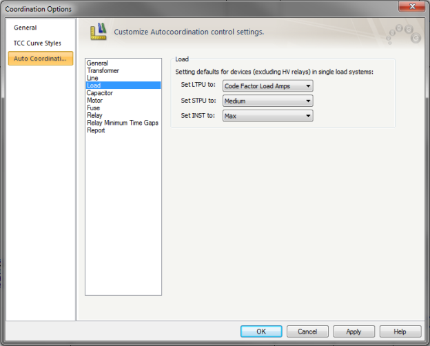
Figure 4: Coordination Options - Load
These options control how coordination is handled for single loads.
Set LTPU to: Select the type of load current calculation to use to set LTPU. The following choices are available:
Set STPU to: Select one of the following STPU settings when coordinating with a single load: Min, Medium, or Max.
Set INST to: Select one of the following INST settings when coordinating with a single load: Min, Medium, or Max.

Figure 5: Auto Coordination Options - Capacitor
Minimum gap between inrush and relay: Set the minimum time gap in seconds between a capacitor’s inrush with a relay to ensure selective coordination. The range is from 0.01 to 10 seconds.
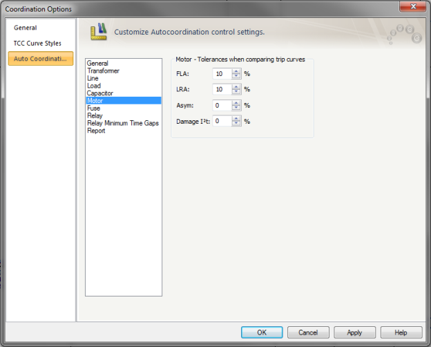
Figure 6: Auto Coordination Options - Motor
Use to set tolerances when comparing trip curves.
FLA: Trip curve will be set outside tolerance boundary when comparing with Motor FLA. The range is –50 % to 50 %.
LRA: Trip curve will be set outside tolerance boundary when comparing with Motor Locked Rotor Amps (LRA). The range is –50 % to 50 %.
Asym: Trip curve settings will be set outside tolerance boundary when comparing with Motor Asymmetrical inrush amps. The range is –50 % to 50 %.
Damage I2T: Sets the minimum gap between the protective device trip curve and the thermal I^2T damage curve of the motor. The range is –50 % to 50 %.
Note: When coordinating protective devices at low voltage, EasyPower assumes the maximum downstream motor size to be 250 HP.
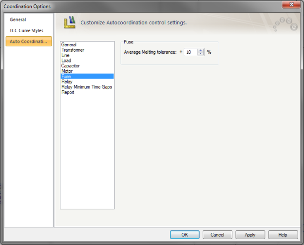
Figure 7: Auto Coordination Options – Fuse
Average Melting tolerance: Used only if the fuse curves are average melting curves. Tolerance enables program to set boundary for fuse curve coordination. The tolerance range is from –50 to 50.
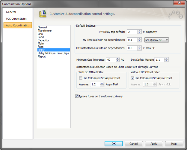
Figure 8: Auto Coordination Options – Relay
HV Relay tap default: When a relay has only cables as downstream equipment, the Tap is set to the specified value times the ampacity of cable.
HV Time Dial with no dependencies: When a relay does not have dependencies, its time dial is set such that the relay trips close to the specified time at the maximum short circuit current available at the CT for the relay. You can also have the time dial set at the specified value instead of basing it on the short circuit current.
HV Instantaneous with no dependencies: The instantaneous is set to the specified multiple of maximum short circuit current.
Minimum Gap Tolerance: The desired minimum time difference between two relays is the sum of Over Travel time, Safety Margin, Auxiliary relay time, and circuit breaker opening time. The time dial settings available in a relay may not provide the exact desired minimum time difference. This Minimum Gap Tolerance enables you to set the time delay of the relay up to the specified percentage higher than the desired minimum time. For example, the desired time difference between two relays is 0.283 seconds. If the Minimum Gap Tolerance is 20%, the program lets the upstream relay time dial to be set such that the time difference is not greater than 0.33 seconds (0.283 + 20%).
Inst Safety Margin: This is the factor used in setting instantaneous pickup. A factor of 1.1 corresponds to a 10% tolerance. For example, if the downstream relay has instantaneous pickup of 3000 Amps, then the upstream relay pickup needs to be higher than 3300 Amps (3000*1.1).
Tap Precision: Select the number of taps/pickup settings program processes through to determine the optimal relay curve settings. There are three (3) precision selections:
Instantaneous Selection Base on Transformer Short Circuit Let-Through Current
With DC Offset Filter: Solid state relays typically have dc offset filters so that trip characteristics are based only on the AC component of currents. The relay library has data indicating whether the relay has a dc offset filter. The DC component may not be completely filtered.
Use Calculated SC Asym Offset: When this check box is selected, the programs uses the asymmetrical currents (with dc component) it calculates. If the check box is not selected, the offset specified in the field below is used.
Assume- Asym Mult: If the checkbox “Use Calculated SC Asym Offset” is unchecked, then the specified value will be used.
Without DC Offset Filter: Relays that do not have dc offset filters, respond to the asymmetrical current.
The time gap between two protective devices is to ensure selective coordination. It is dependent on the combination of devices. The spreadsheet lists different combination of protective devices consisting of induction disk (ID) and solid state (SS) relays, fuses and LV breakers. The minimum time gap is sum of the Overtravel, Safety Margin, Auxiliary and breaker opening time.
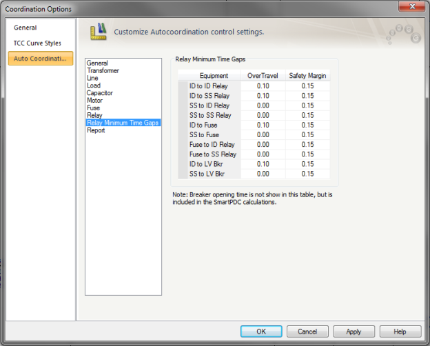
Figure 9: Auto Coordination Options – Relay Minimum Time Gap
The Auto Coordination Report enables you to observe the changes to protective device settings along with comments from the auto coordination process. EasyPower creates separate reports for phase and ground auto coordination.
The report contains two tables for each protective device that is coordinated during the auto coordination process. The Coordinated With table lists all the dependent equipment with which the selected protective device was coordinated. The comments accompanying each specified dependent equipment gives additional details that were used by EasyPower in the auto coordination of the protective device.
The Suggested Settings table for the coordinated device shows the Old and New Settings for each individual setting section. Each setting also has additional comments which include explanations as to why the new setting was selected. Comments may include other dependent equipment settings used to for coordination, NEC codes, or many other additional reasons. Comments in both tables that are in gold font are warnings while comments in red font are violations. Warnings and violations need to be reviewed and addressed.
It is advisable that you completely review each table for each coordinated protective device in the Auto Coordination Report to make sure all results are accurate and meet required specifications.
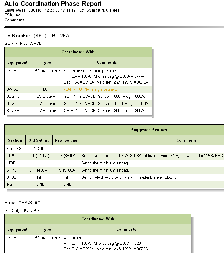
Figure 10: Auto Coordination Phase Report
After the Auto Coordination Report is created you can print it directly from EasyPower, copy it directly to your report, or save it as an HTML file.
 Print from the Text Report ribbon.
 EasyPower button and select Save As.
| Auto-Coordination | |
| Auto Coordination Process | |
| Protective Devices that can be Auto Coordinated |