 Maximize to fill your screen with the one-line.
 Coordination to open the Coordination focus.
This tutorial will guide you through several of the main features in EasyPower’s PowerProtector™ coordination program.
Maximize to fill your screen with the one-line. Coordination to open the Coordination focus. Open TCC.
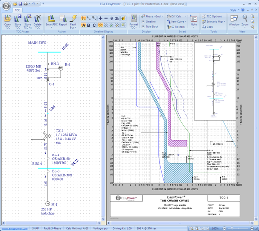
Figure 1: TCC Plot
The EasyPower TCC window supports dynamic dragging of all protective device curves. This provides an easy and smooth interface for changing the equipment settings.
Hover over the relay R-6 until a double-headed arrow appears, and then drag the curve up and down. The relay time dial changes dynamically. The tooltip indicates the latest time dial setting.
Note: Relay settings can also be modified through the relay dialog box by double-clicking on the relay.
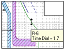
Figure 2: Dynamic Coordination of TCC Curves
There are two one-lines in the TCC window – one located inside the TCC and one located to the left of the TCC. (We refer to them as the “inside one-line” and “left one-line” in this tutorial.)
The inside one-line always displays a zoomed-out view of the left one-line. This provides WYSIWYG screen viewing of the printed TCC. This inside one-line box can be moved and resized as shown in figure below.
In the left one-line, equipment items can be moved, dragged or modified using the common interface typical to all EasyPower one-lines. The inside one-line is simply a picture of the left one-line.
Note: Moves and drags made in the left TCC one-line do not affect the master one-line created in the Database Edit focus.
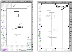
Figure 3: Dragging and Resizing the TCC One-line
The TCC window is integrated directly with the short circuit analysis of EasyPower. Fault currents display on the TCC one-line just as in the master one-line. In addition, these calculated short circuit currents automatically clip the TCC curves when specified to do so in the TCC Options.
Short circuit fault and remote currents display for the fault on SWG-4. In addition, the TCC tick marks and clipping currents automatically adjust based on the fault and remote currents.
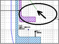
Figure 4: Relay Curve Clips at Remote Current
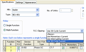
Figure 5: TCC Clipping Modification in the Temporary Relay Data Dialog
The relay curve now clips at the 30 cycle fault current rather than the maximum ½-cycle fault current. This provides increased flexibility and accuracy when determining the proper coordination settings for the relay.
Note: You might want to experiment with changing some of the other settings in the Temporary Relay Data dialog box. For example, typing in new Function ID names adds multiple function curves to the relay. In the Settings tab, the relay Instantaneous and Time Dial settings are modified. In the Appearance tab, you can change the curve colors and styles.
 Fault Bus(es).
The maximum fault currents for each bus are shown.
Fault Bus(es).
The maximum fault currents for each bus are shown. Notice the tick marks and clipping points also adjust in the TCC.
 TCC Options. In the TCC Options dialog box, select
User-Specified, and then click OK.
TCC Options. In the TCC Options dialog box, select
User-Specified, and then click OK.
The TCC tick marks and clipping points update based on the user-specified currents in each protective device dialog box. For example, double-click on the blue solid state trip (SST) curve, select the Short Circuit tab, and notice the user-entered 22kA.
 Print. In the
Print TCC dialog box select one of the print options shown below and then click OK.
Print. In the
Print TCC dialog box select one of the print options shown below and then click OK.
The TCC plot prints WYSIWYG, or exactly what the screen displays. This provides tremendous speed and ease-of-use to the process of producing clean professional printouts.
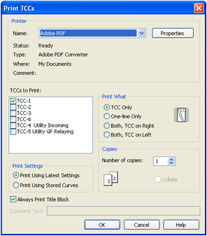
Figure 6: Print TCCs Dialog Box
To change protective device settings, double-click on any TCC curve or one-line item. This brings up a dialog box which enables you to change equipment settings and curve characteristics.
Note: The full list of cable, transformer, and motor parameters are available in the Database Edit focus. If you want to view these while in the TCC, right-click on the curve and select DB Info.
TCCs are created by selecting one-line equipment and clicking a button.
 Plot TCC. A new TCC window appears.
Note: You can drag the text boxes to different locations to improve readability.
This has been a brief overview of the EasyPower Coordination program, PowerProtector™. You might want to experiment with the other TCCs stored in the Protection-1.dez file. Also, other features are available in PowerProtector™ that were not discussed at length in this tutorial. A few are listed below:
Note: The standard EasyPower library already has a full array of TCC curves, but an easy interface exists for curve entry if needed.
If you have any questions or comments on the PowerProtector™ program, please e-mail us at techsupport@EasyPower.com.