 Maximize to fill your screen with the one-line.
 Short Circuit to open the Short Circuit focus.
In this tutorial, you will be shown how to use several of EasyPower’s short circuit analysis features.
To run short circuit analysis, you must be in the Short Circuit focus.
Maximize to fill your screen with the one-line. Short Circuit to open the Short Circuit focus.Double-click on BUS-3. The bus turns light blue and displays fault currents in symmetrical kilo-amps. As shown in Figure 1, the motor contributes 0.863kA and the cable 4.481kA to the fault. The total bus fault current, shown at a forty-five degree angle, is 5.344kA.
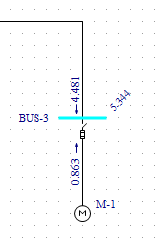
Figure 1: Calculating Fault Currents
There are several different methods to fault buses while in Short Circuit focus:
 Fault Bus(es).
Note: To select a single bus, click on it. To select extra buses, click on them while holding down the SHIFT key.
Fault Bus(es) without selecting any buses. This runs a batch fault on all the buses in your
system. Remote V/I. The remote currents are 0.896kA on the primary side of the transformer and 4.481kA on the secondary
side (as shown in the figure below). The remote voltages, shown at a forty-five degree angle, are 0.643pu on BUS-1 and 0.000pu on
BUS-2.
Remote V/I. The remote currents are 0.896kA on the primary side of the transformer and 4.481kA on the secondary
side (as shown in the figure below). The remote voltages, shown at a forty-five degree angle, are 0.643pu on BUS-1 and 0.000pu on
BUS-2.
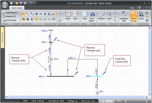
Figure 2: Remote V/I
ANSI Standards list three distinct time intervals for short circuit currents. These are momentary (½ cycle), interrupting
(5 cycle), and 30 cycle. By default, EasyPower displays the momentary currents, as indicated by
 Momentary selected in the toolbar.
 Interrupting to view the interrupting results. (They are displayed next to the ½-Cycle
currents.) Note that the overall bus current magnitude drops to 4.826kA due to the decay of the motor contribution.
Interrupting to view the interrupting results. (They are displayed next to the ½-Cycle
currents.) Note that the overall bus current magnitude drops to 4.826kA due to the decay of the motor contribution. 30 Cycle to view the 30 cycle currents (see figure below). Notice that the motor
current contribution decays to zero leaving only 4.481kA from the utility.
30 Cycle to view the 30 cycle currents (see figure below). Notice that the motor
current contribution decays to zero leaving only 4.481kA from the utility.
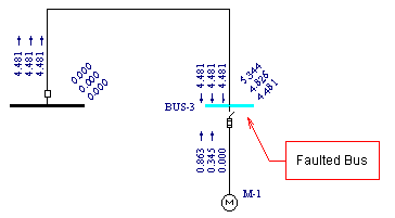
Figure 3: ½ -Cycle, Interrupting, and 30 Cycle Currents
The currents calculated to this point have been 3-phase currents. EasyPower also calculates unsymmetrical faults. According to convention, single line-to-ground fault calculations assume the A-phase is faulted. For double line-to-ground and line-to-line faults, convention says that phases B and C are faulted. Refer to Elements of Power System Analysis by William D. Stevenson, Jr. for examples of unsymmetrical fault calculations.
 Interrupting and
 30 Cycle to remove those selections, and leave
Momentary selected.
30 Cycle to remove those selections, and leave
Momentary selected. Line to Ground.
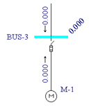
Figure 4: Single Line-to-Ground
 Double Line to Ground. The green dots in the button indicate ground fault.
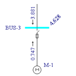
Figure 5: Double Line-to-Ground
 Line to Line. Faults are now line-to-line faults. The yellow dots in the button
indicate this is not ground fault.
Line to Line. Faults are now line-to-line faults. The yellow dots in the button
indicate this is not ground fault.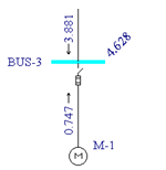
Figure 6: Line-to-Line Fault
 SC Reports from the ribbon.
  3-Phase to return to 3-phase fault calculations. Fault Bus(es). A high voltage momentary text report window is created. You can view
this report either by selecting
HV Momentary Report for ‘simple.dez (Base case)’ from the Window button or by double-clicking on the
window icon created in the lower left corner. Your text report will look similar to that in the figure below.
3-Phase to return to 3-phase fault calculations. Fault Bus(es). A high voltage momentary text report window is created. You can view
this report either by selecting
HV Momentary Report for ‘simple.dez (Base case)’ from the Window button or by double-clicking on the
window icon created in the lower left corner. Your text report will look similar to that in the figure below.
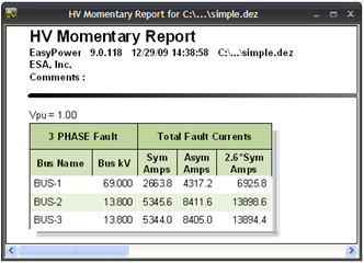
Figure 7: Short Circuit Text Report
SC Options from the ribbon and select the One-line Output tab.
In this dialog (shown in the figure below) you can specify asymmetrical fault currents to be displayed on the one-line. You can also show fault currents in Per-Unit or MVA units and remote voltages in kV units.
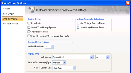
Figure 8: Short Circuit One-line Output Dialog Box
Here you can specify other short circuit settings for your fault calculations. These changes take effect on all subsequent faults after closing this dialog box.
This has been a brief overview of EasyPower’s short circuit program. The EasyPower User’ Manual and Help system cover these and other short circuit features in greater depth.