 Maximize to fill your screen with the one-line.
 Coordination in the ribbon to open the Coordination focus.
This tutorial guides you through several of the main features in EasyPower’s SmartPDC™ module (Automated Protective Device Coordination, or Auto Coordination). If you have not worked through the Protective Device Coordination tutorial, we recommend you do so before continuing. SmartPDC™ automates the protective device coordination and setting process, providing detailed coordination with one-touch simplicity for LV and HV systems.
Note: The SmartPDC™ feature is not available in the Demo version of EasyPower.
To use the SmartPDC™ feature, you must be in the Coordination focus.
Maximize to fill your screen with the one-line. Coordination in the ribbon to open the Coordination focus.Tip: Hold down the mouse wheel while dragging to move the view of the one-line. You can roll the mouse wheel or use the zoom controls in the lower right side of the window to control how large the one-line items appear.
This opens the SmartPDC-1 plot window, in which you can view the time current curve for the selected items.
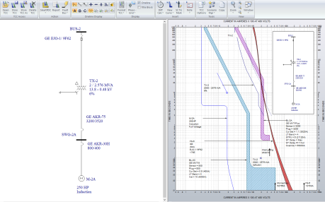
Figure 1: One-line and SmartPDC-1 Plot
 SmartPDC. All protective devices with TCC data are coordinated starting with the furthest downstream
device and working upstream. Note how the TCC curves change from before.
SmartPDC. All protective devices with TCC data are coordinated starting with the furthest downstream
device and working upstream. Note how the TCC curves change from before.Note: If you do not select one or more protective devices in the one-line before you click
 SmartPDC, all protective devices are coordinated. To coordinate a
single protective device or group of protective devices, select the devices first.
SmartPDC, all protective devices are coordinated. To coordinate a
single protective device or group of protective devices, select the devices first.
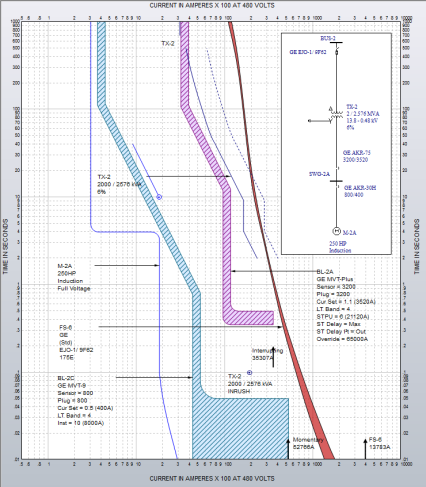
Figure 2: TCC Curves After SmartPDC™ Coordination
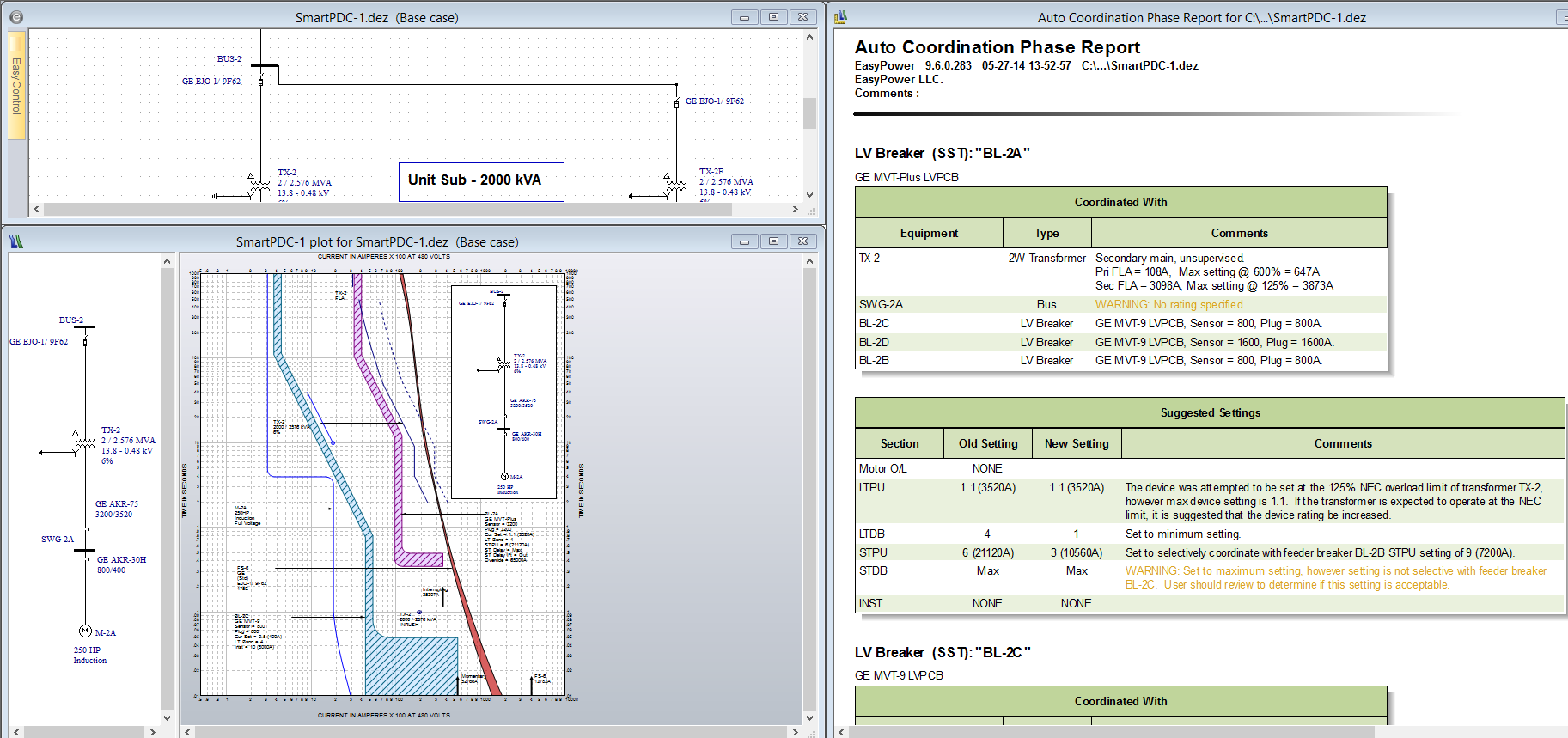
Figure 3: Arrange for Auto Coordination View
The Auto Coordination Phase Report shows all equipment information used to coordinate each device and the suggested settings for each coordinated device. Errors are red and warnings are yellow in the Comments column.
Note: We recommend that this process be repeated to auto coordinate the entire system. Coordinate small radial subsystems and work upstream throughout the system.
Maximize to fill your screen with the SmartPDC-1 (Base case) one-line. SmartPDC.
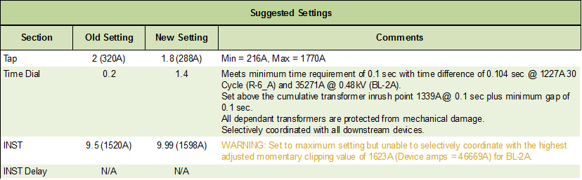
The relay tap setting is found using the calculated NEC Min and Max values as limits. For each tap, the program cycles through time dial and instantaneous ranges to determine the best coordinated relay settings.
The time dial settings require a minimum gap time between the relay and downstream protective devices. The minimum time between two protective devices may be set in the relay section of Auto Coordination Options.
Relay instantaneous is set above the highest short circuit clipping value for all dependent components.
To set auto coordination options while viewing the TCC ribbon, click the arrow below
SmartPDC and select  SmartPDC Options. If you are in the Coordination focus, select
 PDC Options and then select the Auto Coordination tab to view the options.
The options are shown in the figure below. The Auto Coordination Options dialog box has various categories of settings. Select the category at the left column to view settings options. Your coordination results can be greatly affected by adjusting the options. For more information on the options, refer to the Help topic, Auto Coordination Options.
Phase and Ground Auto Coordination analysis options are set in the General section of Auto Coordination Options. Phase Auto Coordination is described throughout this tutorial.
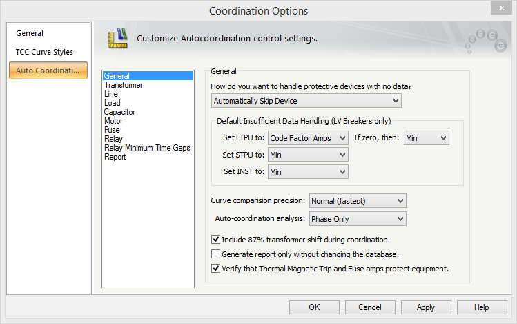
Figure 4: Auto Coordination Options
If the settings for a protective device have been previously coordinated, you can lock a protective device from being modified from auto coordination. To lock a protective device from auto coordination, right-click on the device symbol in the one-line and under Auto Coordinate, select Locking > Lock Auto Coordination. This action selects the Lock Auto-Coordination check box in the protective device dialog box.
To observe this, right-click on LV breaker BL-2A on the one-line and select DB Info. The check box is located in the upper right of the data dialog box. The Lock Auto-Coordination check box is in the same location for a fuse.
Note: When viewing DB Info in the Coordination focus, the check box can be viewed but not changed.
To select the Lock Auto-Coordination check box in MCCs and panels, open each protective device while in the Database Edit focus and select the check box.
To lock a function in a relay from auto coordination, open the Relay Data dialog box. On the Settings tab, select the Lock Auto-Coordination check box for each Function ID. If it is a multi-function relay, only the functions containing a selected check box are omitted from auto coordination.
To lock multiple protective devices from auto coordination, while in the Coordination focus, select the protective devices on the one-line. Click
the arrow below
 SmartPDC and select
  Lock Auto Coordination. The same method can be used to unlock protective devices to allow them to be auto coordinated.
There are two ways to undo the changes created by auto coordination process:
 button on the Quick Access Toolbar.
There is also an option to create an Auto Coordination Report containing the suggested settings without making temporary changes to the database. In the General section of Auto Coordination Options dialog box, select the Generate report only without changing the database check box to prevent changes from being made when the report is generated.
This has been a brief overview of the EasyPower Auto Coordination program. Ground coordination is also available in SmartPDC™ but was not discussed in this tutorial.
If you have any questions or comments on the SmartPDC™ program, please contact techsupport@EasyPower.com.