 SC Options from the ribbon and select the Arc Flash Hazard tab.
To select arc flash hazard options, click SC Options from the ribbon and select the Arc Flash Hazard tab.
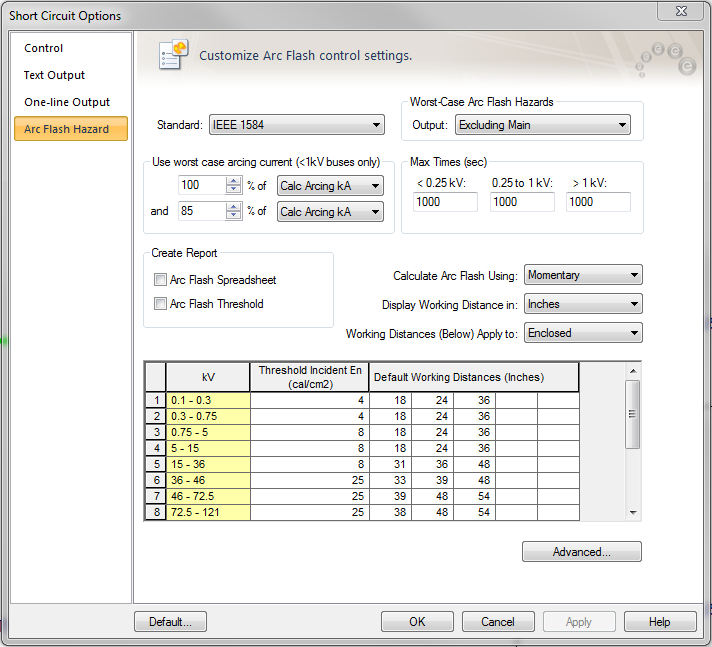
Figure 1: Short Circuit Options – Arc Flash Hazard tab
Standard: You can select any of the following standards for calculation method.
The IEEE 1584 equations are applicable up to 15kV. Above 15kV, the program uses the Ralph Lee method, and the distance “X’ factor and the gap from the library do not apply. This method has the distance exponent of 2.
Worst-Case Arc Flash Hazards: EasyPower obtains the arcing time from the upstream protective device of the faulted bus. The program uses the coordination feature PowerProtector™ to calculate the trip time for the estimated fault current passing through the protective device. This is the most accurate method. This option works only if you have the PowerProtector™ feature included in your EasyPower.
Output: Select one of the options in the drop down box to evaluate the arc flash hazard results for any bus in the following ways:
Note: Panels typically have the main breaker, bus bar and feeder breakers housed inside the same enclosure. Opening the front cover would expose a worker to arc on the line side of the main breaker. To simulate this hazard, select the Excluding Main option, since the device to interrupt faults would have to be an upstream device.
Use the worst case arcing currents: IEEE 1584 recommends using two scenarios – one with 100% of estimated arc current and the other with 85% of estimated arc current. This is due to the fact that arc currents may be random and usually vary by some proportion about the estimated value. For inverse-time over-current characteristics of protective devices, the arcing time is greater for smaller currents than it is for larger currents. Since the incident energy of arc faults is more sensitive to arcing time than it is to arc currents, it is necessary to obtain a more accurate arcing time. IEEE 1584 proposes taking 85% of the initial estimate of the arc current.
EasyPower enables you to consider two scenarios of arc currents. EasyPower calculates both scenario and automatically reports the worst case of incident energy, thus providing conservative results.
The IEEE 1584 recommended 100% and 85% of arc current are default values. You may change these ratios by typing in the fields or using the buttons to increase or decrease the values.
When 100% or the upper value yields greater arc flash incident energy, then the text results are displayed in black in the Arc Flash Report spreadsheet. When 85% or the lower value yields greater incident energy, the text is displayed in pink.
Max Times (sec): The Max Time is the maximum time that the program uses to calculate the incident energy. If the trip time calculated as per device TCC is less than the specified maximum time, then the device trip time is used. If the device trip time exceeds the specified maximum time, then the Max Time value is used. The default maximum time is 1000 seconds.
Calculate Arc Flash Using: Specify the fault current used during arc flash calculations. Select between Momentary, Interrupting, and 30 Cycle fault currents or the Integrated method.
Display Working Distance in: You can select the units for working distance from any of the following. This affects the results such as arc flash boundary as well.
Working Distances (Below) Apply to: You can specify separate working distances for open air and enclosed space. Select the appropriate choice to view or edit the values in the spreadsheet. Typically for medium voltage, switches and fuses at open air may be operated from a greater distance.
Arc Flash Spreadsheet: Select this check box to obtain spreadsheet report of arc flash hazard calculations when faulting buses.
Show: Fault current displayed in arc flash hazard report.
Arc Flash Threshold: Check this box to obtain a report of buses that exceed the arc flash threshold incident energies specified in the options. You can specify any incident energy as the threshold for various voltage levels by typing in the values in the spreadsheet in the Arc Flash Hazard options. All equipment exceeding the hazard thresholds will be displayed in red on the one-line.
Threshold Incident energy: For every voltage level you can specify the threshold incident energy. Equipment with incident energies exceeding the threshold values will be highlighted in red in the one-line output and they will be reported in the Arc Flash Threshold Report. This provides instant notification of a danger condition. All equipment with incident energies exceeding the threshold values are displayed in red on the one-line.
Default Working Distances: For every voltage level, you can specify up to five working distances for which the incident energy will be provided in the Arc Flash Report. In the one-line output, results will be shown only for the shortest working distance, which has the highest incident energy.
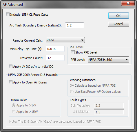
Figure 2: Advanced Arc Flash Options
Include 1584 CL Fuse Calcs: Use IEEE 1584 equations for current limiting fuses to determine incident energy. This method calculates the let through arc flash incident energy based on bolted fault currents and UL class of fuse. Equations are available for classes L and RK1. This is applicable only for low voltage systems. The fuse equations are effective only when the fault current is high compared to the minimum fault current required for current-limiting. When the fault current is well below the current-limiting range of the fuse, the standard arc flash equations are used. When the 1584 CL Fuse Calculations are used for any bus, the Arc Flash Hazard Report shows the bolted fault current but not the arc current and the trip times, since these values are not used to determine the incident energy.
Note: The IEEE 1584 CL fuse equations provide incident energy at 455mm. The default low voltage working distance in the program is 18 inches (which is equivalent to 457.2 mm). Therefore, the results for 18 inches will be slightly different from the results for 455mm.
Arc Flash Boundary Energy (cal/cm2): NFPA-70E specifies two types of arc flash boundaries. When the arcing time is less than 0.1 second, the boundary is at a distance at which the incident energy is less than or equal to 1.5 cal/cm2. When the arcing time is greater than 0.1 second, the boundary is at a distance at which the incident energy is less than or equal to 1.2 cal/cm2. These are the default values. You can change them if necessary.
Remote Current Calc: EasyPower supports two different methods for determining the remote current through protective devices during an arc fault:
Minimum Relay Trip Time: This is the minimum trip time used for relays. The default value is 0.016s. If the relay trip time in a TCC shows less than this specified value, this minimum time is used in arc flash. One-lines created in versions previous to 8.0.2.305 will show a minimum relay trip time of 0.01 seconds. You can change this option.
Traverse Count: This is the maximum number of buses the program will traverse upstream from the faulted bus to find the trip device. The default count is 12, to optimize for speed. You can increase the Traverse Count value if necessary. Examples of where it may be necessary to increase the Traverse Count include long distribution feeders with multiple taps, busways (bus ducts) with multiple bus plugs, underground distribution systems, and wind farms.
NFPA 70E 2009 Annex D.8 describes estimating the incident energy for overhead open air systems 1kV to 800kV. These calculations are based on open air phase-to-ground arcs.
Apply to Open Air Buses: Enables calculations for open air buses based on the Annex D.8 method.
Minimum kV:
Working Distances:
Fault Types: These are multipliers used to estimate the incident energies for 3-phase fault and line-to-line faults for arcs on open air buses.
| Arc Flash Hazard Analysis | |
| Calculating Arc Flash Hazards / Currents |