 Maximize button on the upper-right to make the window fill the screen. To make the one-line window fill the EasyPower session, click its maximize button also.
This tutorial describes the basic steps to create a one-line. For more detailed instructions, refer to "Making One-Line Diagrams" and "Your First EasyPower One-line" in Help.
After you start EasyPower, the session window opens. Click the window's Maximize button on the upper-right to make the window fill the screen. To make the one-line window fill the EasyPower session, click its maximize button also.
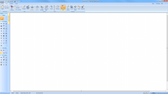
Figure 1: EasyPower Session
EasyPower performs calculations using the concept of “bus." A bus can represent not only a bus bar, but also a connection point (or terminal of a piece of equipment). You can also think of buses as nodes. The central equipment type of every one-line is the bus. A bus defines the connection point for all types of equipment. Each piece of equipment must be connected to a bus when creating the one-line.
 Bus in the Equipment Palette—the pointer changes into a bus symbol. Place three buses as
shown in the figure below by clicking the mouse. Don't worry about the utility yet—we'll add it in a moment.
Bus in the Equipment Palette—the pointer changes into a bus symbol. Place three buses as
shown in the figure below by clicking the mouse. Don't worry about the utility yet—we'll add it in a moment.Note: Depending on your settings, you may need to click
 Select in the Equipment Palette or press ESC on the keyboard between adding each bus—the pointer changes into a select pointer
  , indicating
that you are no longer adding items.
, indicating
that you are no longer adding items.
 MCC and place a motor control center on the one-line as shown below.
  Panel and place a panel on the one-line as shown below.
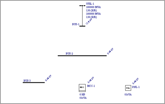
Figure 2: Adding Buses, MCCs, and Panels
You can now move and re-size your buses. To move your buses and ID names, drag them with the mouse while the select pointer is active. To lengthen or shorten your buses, drag either end of each bus with the mouse.
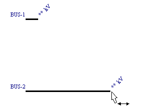
Figure 3: Adjusting Bus Sizes
Enter bus data by double-clicking on each of the bus symbols with the select pointer . The Bus Data dialog box is displayed each time and you can enter the kV for the bus. Use 13.8 kV for the top bus and 0.48 kV for the others. You may also
change the ID names.
Tip: You can set a default kV for new buses by selecting Tools > Equipment > Bus from the ribbon.
You can also copy and paste bus data. To do this:
. The bus turns green to indicate it is selected.  Copy.
Copy. Paste. if needed and drag the symbol into position.
![]()
Figure 4: Adding a Transformer
active, use the left mouse key to drag the transformer's
remaining leader to the middle bus (see figure above). After it connects, drag the transformer symbol up so it is centered
between the two buses. Cable on the Equipment Palette—the pointer changes into a crosshair. Put the crosshair on
the middle bus and click the left mouse button (but don't release it yet). This sets one end of the line. Now drag the
crosshair to the left bottom bus (as shown in the figure below) and release the mouse button. This places the cable.
Cable on the Equipment Palette—the pointer changes into a crosshair. Put the crosshair on
the middle bus and click the left mouse button (but don't release it yet). This sets one end of the line. Now drag the
crosshair to the left bottom bus (as shown in the figure below) and release the mouse button. This places the cable.
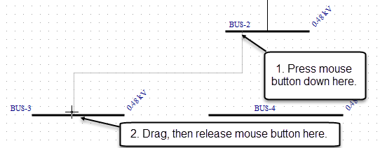
Figure 5: Adding Cables
 Motor on the Equipment Palette—the pointer changes into a motor symbol.
 Utility on the Equipment Palette—the pointer changes into a utility symbol., double-click on the utility to enter utility data.
 LV Breaker on the Equipment Palette—the pointer changes into a low voltage breaker
symbol.
LV Breaker on the Equipment Palette—the pointer changes into a low voltage breaker
symbol.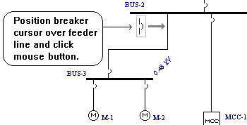
Figure 6: Adding Feeder Breakers
Click  Zoom Out Full to center your entire one-line on your screen.
Congratulations! You just entered a power system one-line with EasyPower. You can apply what you have learned to your real-world systems. For an example of a larger completed one-line, open the Bigger.dez database in the Samples directory. You can experiment running analysis with this file by selecting Short Circuit, Power Flow, or Harmonics from the ribbon.
For more information on creating one-lines and running analysis, click  Help or press F1 while viewing any window in EasyPower to enter EasyPower's fully detailed Help system. You can find additional detailed instructions in the "Making One-Line Diagrams" and "Your First EasyPower One-line" topics in Help.