Figure 1: Auto Design Options - General
Auto Design options let you select design templates, calculation methods, and default values for your design. To select the options, select Tools > Options > Auto Design.
There are 5 categories of options:

Figure 1: Auto Design Options - General
| Option | Description |
|---|---|
|
Design Library Sheet |
Select the design template you want to use. The design templates are stored as design sheets in the standard library (Stdlib.mdb). The library has a default design sheet named “Generic.” You can create your own design templates in the library. For details on creating or editing design sheets, see Design Library. |
|
Generate Report Only Without Changing Data |
This enables you to view comments regarding existing design (size/ratings) of equipment, without changing design (data). When this is not selected, the equipment sizes/ratings can be changed upon running Auto Design. |
|
Create Bill of Materials Report |
Creates a Bill of Materials report for the items that are auto-designed. |
|
Downstream load based on |
Select the type of load current calculation to use to size equipment. The following choices are available:
|
|
Sizing MCCs/Panels on One-line |
MCC and Panel schedules include different components such as main (breaker/fuse), bus, feeder breakers/fuses, feeder cables, etc. You can select what items to size by selecting the appropriate choice:
|
|
Default Motor Starter |
Selects which type of starter to use in the MCC feeder description when sizing MCC. |
|
SC Threshold (%) |
When the estimated short circuit current through an equipment is greater than the specified threshold value of the equipment short circuit rating, a warning is provided in the report. A threshold of 20% corresponds to 0.8 * Equipment Rating. |
|
Show extended comments for series coordination |
This option provides more detailed comments when performing series coordination between protective devices. |

Figure 2: Auto Design Options - Lines
| Option | Description |
|---|---|
|
Tap Rule Length (ft) |
Length of the conductor from tapping point to downstream protective device that does not need to be protected by a protective device. |
|
When choosing cables, assume |
Select one of the options below. Design for both systems can be specified in the design library.
|
|
Default Cable Length (ft) |
The Auto Design feature automatically enters the default cable length if the cable length is not already specified. |
|
Sizing Lines Protected by SSTs |
Size based on tap/plug rating: Cables are sized based on upstream breaker rating, which is defined by the sensor tap or the rating plug of the solid state trip. Size based on adjusted LTPU: If the upstream solid state trip has an adjustable long time pickup (LTPU) setting, then sizing cable based on the LTPU amps can enable you to economize on cable size. |

Figure 3: Auto Design Options – Protective Device
| Option | Descripton |
|---|---|
|
When choosing breaker pickup setting, assume |
Breakers with adjustable pickup settings can be set as the highest or lowest possible pickup that is equal to or greater than the design Amp value.
|
|
Size Feeder Breakers |
Select the criteria for sizing feeder breakers.
|

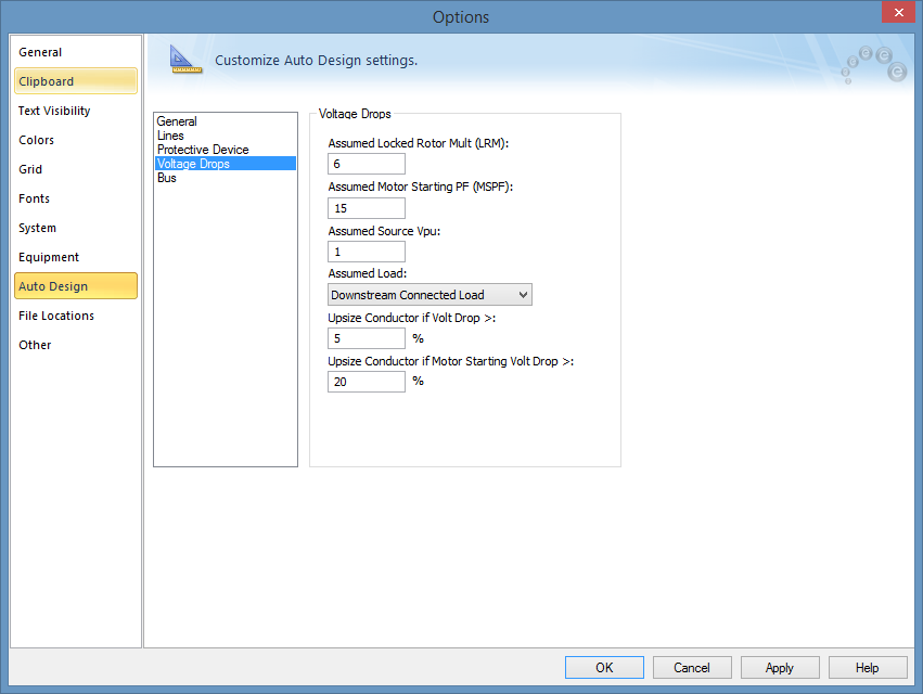
Figure 4: Auto Design Options – Voltage Drop
Auto design lets you select cables of higher rating if the voltage drop at the downstream end of the cable is greater than a user-specified value. The voltage drop is defined as follows:
Voltage Drop = (Base kV – Calculated Voltage)/ Base kV * 100%
| Option | Description |
|---|---|
|
Assumed Locked Rotor Mult (LRM) |
This value, multiplied by the full load amps of motors, provides the starting (inrush) current. This value is used for all motor circuits for voltage drop calculation while sizing cables. |
|
Assumed Source Vpu |
The per-unit voltage at the source end of the cable. |
|
Assumed Load |
Type of amps calculation to use for voltage drop calculation. Choices are:
|
|
Upsize Conductor if Volt Drop > |
If the voltage drop due to load is greater than the specified value, the program selects the next larger cable in order to keep the voltage drop within specified limits. To avoid upsizing cables based on voltage drop, the edit field must be blank. |
|
Upsize Conductor if Motor Starting Voltage Drop > |
If the voltage drop due to motor starting is greater than the specified value, the program selects the next larger cable so that the voltage drop is kept within specified limits. Important: To avoid upsizing cables based on motor starting voltage drop, the edit field must be blank. |

Figure 5: Auto Design Options - Bus
| Option | Description |
|---|---|
| <Other> Bus Types | For buses defined as type Other, you can allow or restrict sizing. |
| Auto Design |

|