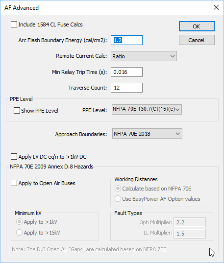
Figure 1: Advanced Arc Flash Options
Figure 1: Advanced Arc Flash Options
| Option | Description |
|---|---|
|
Include 1584 CL Fuse Calcs |
Use IEEE 1584 equations for current limiting fuses to determine incident energy. This method calculates the let through arc flash incident energy based on bolted fault currents and UL class of fuse. Equations are available for classes L and RK1. This is applicable only for low voltage systems. The fuse equations are effective only when the fault current is high compared to the minimum fault current required for current-limiting. When the fault current is well below the current-limiting range of the fuse, the standard arc flash equations are used. When the 1584 CL Fuse Calculations are used for any bus, the Arc Flash Hazard Report shows the bolted fault current but not the arc current and the trip times, since these values are not used to determine the incident energy. Note: The IEEE 1584 CL fuse equations provide incident energy at 455mm. The default low voltage working distance in the program is 18 inches (which is equivalent to 457.2 mm). Therefore, the results for 18 inches will be slightly different from the results for 455mm. |
|
Arc Flash Boundary Energy (cal/cm2) |
The boundary is at a distance at which the incident energy is less than or equal to 1.2 cal/cm2. This is the default value. You can change it if necessary. |
|
Remote Current Calc |
EasyPower supports two different methods for determining the remote current through protective devices during an arc fault:
|
|
Minimum Relay Trip Time |
This is the minimum trip time used for relays. The default value is 0.016s. If the relay trip time in a TCC shows less than this specified value, this minimum time is used in arc flash. One-lines created in versions previous to 8.0.2.305 will show a minimum relay trip time of 0.01 seconds. You can change this option. |
|
Traverse Count |
This is the maximum number of buses the program will traverse upstream from the faulted bus to find the trip device. The default count is 12, to optimize for speed. You can increase the Traverse Count value if necessary. Examples of where it may be necessary to increase the Traverse Count include long distribution feeders with multiple taps, busways (bus ducts) with multiple bus plugs, underground distribution systems, and wind farms. |
| PPE Levels | |
|
Show PPE Level |
If this check box is selected, the PPE level is displayed on the one-line and the Arc Flash Hazard report. |
|
PPE Level |
If you have selected to show the PPE level, you can specify which standard you want to use to specify the level. The levels are defined in the device library. See Defining PPE Levels for more information on customizing the levels. |
|
Approach Boundaries |
Select the standard on which you want to specify approach boundaries. The options are:
|
|
NFPA 70E 2009 Annex D.8 Hazards NFPA 70E 2009 Annex D.8 describes estimating the incident energy for overhead open air systems 1kV to 800kV. These calculations are based on open air phase-to-ground arcs. |
|
|
Apply to Open Air Buses |
Enables calculations for open air buses based on the Annex D.8 method. |
|
Minimum kV |
|
|
Working Distances |
|
|
Fault Types |
These are multipliers used to estimate the incident energies for 3-phase fault and line-to-line faults for arcs on open air buses. |
| Arc Flash Hazard Options | |
| Arc Flash Hazard Analysis | |
| Calculating Arc Flash Hazards / Currents |
|
|