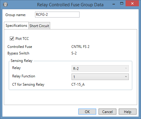
Figure 1: Specifications Tab
This tab lists the equipment and settings required for the functional group. See Relay Controlled Fuse Groups and Relay Controlled Fuse Group Settings for more information.
This dialog box includes the following areas and tabs:

Figure 1: Specifications Tab
This tab lists the equipment and settings required for the functional group. See Relay Controlled Fuse Groups and Relay Controlled Fuse Group Settings for more information.
| Option | Description |
|---|---|
| Plot TCC | Select this check box to plot the TCC for the functional group. If the check box is not selected, the TCC for the functional group is not plotted. However, the controlled fuse and relay are plotted individually if their Plot TCC options are selected. |
| Controlled Fuse | The controlled fuse for the functional group. |
| Bypass Switch | The switch for the functional group. |
| Sensing Relay | |
| Relay Function | The relay function for the relay in the functional group. You can change the function, if needed. For example, on a multifunction relay, you can select a function that meets the phase or maintenance phase requirement (see Relay Controlled Fuse Group Conditions for more information about function requirements). |
| CT for Sensing Relay | The current transformer (CT) for the relay in the functional group. |

Figure 2: Short Circuit Tab
Data entered in this section is used to place tick marks representing short circuit values on the TCC plot.
| Option | Description |
|---|---|
| TCC Clipping | You can clip the time current curve (TCC) for the breaker at the specified current in kA for Momentary (1/2 cycle), 5-cycle or 30-cycle. Select <None> to avoid clipping of the TCC. |
| SC Tick Marks |
Select the appropriate check boxes to display the tick mark on the TCC plot. You can display Momentary, Interrupting and 30 Cycle short circuit values. Enter the corresponding short circuit values in kA in their respective edit fields for phase short circuit. Note: These settings are only used if User-Specified is selected in Coordination Options > General > Default TCC Short Circuit Currents. Otherwise, the values are automatically calculated. |
| Default Phase SC Values |
The short circuit values entered in kA in these fields can be displayed for phase currents on TCC plots. Note: These settings are only used if User-Specified is selected in Coordination Options > General > Default TCC Short Circuit Currents. Otherwise, the values are automatically calculated. |
| Database Technical Reference | Relay Controlled Fuse Group Conditions |
| Functional Groups | Relay Controlled Fuse Group Settings |
| Relay Controlled Fuse Groups | Media Gallery |

|