Specifying Arc Flash Hazard Data for Equipment

You can specify the arc flash hazard data for any equipment by storing the data in an associated bus. The bus may represent the terminals or conductors. Equipment such as MCCs and panels are also modeled similar to buses and they store data for arc flash hazard.

Here, we will demonstrate how to specify arc flash hazard data for a bus. To open the Bus Data dialog box, on the Home tab, click Database Edit, and then double-click on the bus.

Specifying Equipment Type

The Specifications tab of Bus Data dialog box has a Type field. This describes the type of enclosure for arc flash calculations. The equation or parameters for evaluating the incident energy and flash protection boundary may differ with the enclosure type. The choices available include Switchgear, MCC, Panelboard, Switchboard, Open Air, Conductor, NEMA E2 Contactor, Int Switches, VFD, ATS, UPS, and several others.

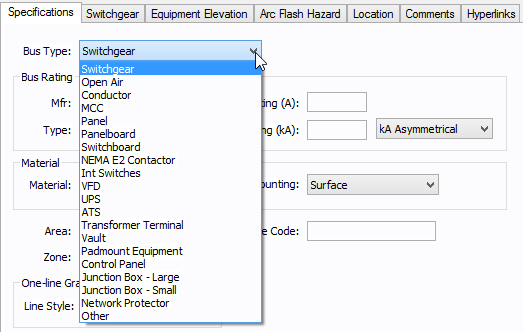
Figure 1: Specifying Equipment Type for Arc Flash Hazard

Specifying Arcing Time

You can specify the arcing time on the Arc Flash Hazard tab. The options are described in the table below.

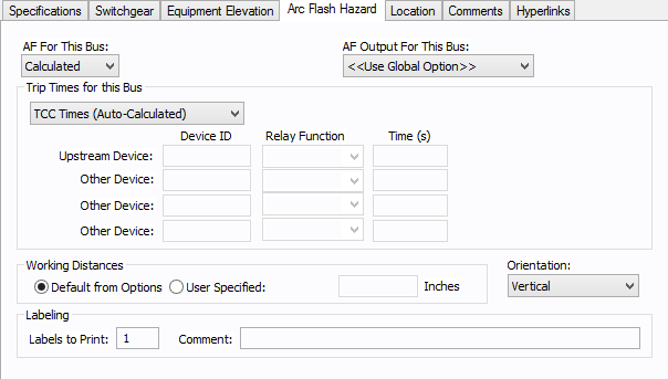
Figure 2: Bus Data-Arc Flash Hazard Dialog Box

Option Description

Arc Flash For This Bus

You can choose to calculate arc flash hazards for this bus, exclude this bus from analysis and reports, or force arc flash incident energies to a specified value.

  • Calculated: By default, when the bus is faulted, arc flash hazard analysis is performed using the calculation method specified in Short Circuit Options.
  • Excluded: No results are provided on the one-line or in the arc flash hazard report. Typical applications for this option are nodes, tap-offs (junctions), where energized work is not required.
  • Forced to: With this option you can enter your own assumed values of incident energies. This can be used for systems with very low voltages and fault levels, at which using industry standard equations may not be practical. You can specify the arc flash boundary for this option in inches. The default is 48 inches.

Trip time for this bus

Predefined Fixed Times: Obtains arc clearing time for the bus from the library default values. This is not the trip time calculated from the TCC of the upstream protective device on the one-line.

User Defined Times: With this option you can specify the protective device clearing time for each bus. The details of arcing time for the bus can be specified in the fields Device ID, Relay Function and Time (s). When this option is selected a time must be specified.

TCC Times (Automatically Calculated): This option uses the trip clearing time from the TCC of the upstream protective device in the one-line to provide arc flash hazard results. The trip clearing time of the equipment where the device is a relay controlled breaker is the sum of the breaker mechanism opening time (for example, 3, 5, 8 cycle), the relay trip time, and any time entered into the Relay Data, System, and Aux Time data fields.

Working Distances

You can select one of the following for working distances for any bus equipment.

  • Default from Options: The working distances specified in Short Circuit Options - Arc Flash Hazard dialog box is used. Typically, most buses would use this global working distance.
  • User Specified: For special cases, when the working distance for any equipment is different from the global working distances in the Short Circuit Options dialog box, user-specified distances can be entered.

More Information

Arc Flash Hazard Analysis  
     

www.easypower.com

EasyPower, LLC

7730 SW Mohawk St.

Tualatin, OR 97062

(503)655-5059

techsupport@easypower.com

feedback@easypower.com

EasyPower knowledge base

EasyPower Version 10.0

Copyright © 2018 EasyPower, LLC. All Rights Reserved.

Help was last updated on 5/22/2018