Tutorial - Short Circuit Analysis (IEC)
In this tutorial, you will be shown how to use several of EasyPower’s short circuit analysis features using IEC-60909 calculations.
IEC Option
To run IEC short circuit analysis, you must set the IEC option.
- From the File menu, click Open File.
Tip: If you are viewing the Start Page, you can click Open One-line instead.
- Open the Simple.dez file in your Samples directory.
- Click
 Maximize on the one-line window, if needed, to fill the session window with the one-line.
- Click
Tools, click
 Options, and then click the
System tab. Select the following:
Options, and then click the
System tab. Select the following:
- Frequency: 50 or 60 Hertz.
- SC Calculation Method: Set this to IEC-60909.
- Units: You can change this to Metric (optional).
- On the One-line Symbols tab, verify that the Base Symbols are set to IEC.
- Click OK to save your changes.
- Click the Home tab and then click
 Short Circuit.
Calculating Fault Currents
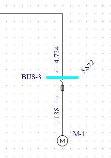
Double-click on BUS-3. The bus color changes to light blue and displays fault currents in symmetrical kilo-amps. As shown in
the figure below, the motor contributes 1.138 kA and the cable, 4.734 kA to the fault. The total bus fault current, shown at a
forty-five degree angle, is 5.872 kA.
Figure 1: Initial Short Circuit Fault
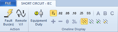
There are several different methods to fault buses while in the Short Circuit focus:
- Double-click on a bus.
- Select a bus or multiple buses (so they turn green) and click
 Fault Bus(es).
Note: To select a single bus, click on it. To select multiple buses, click on each bus while holding
down the
SHIFT key.
- Click Fault Bus(es) without selecting any buses. This runs a batch fault on all the buses in your
system.
Changing the IEC Standard Time Interval
The following currents can be calculated in EasyPower:
- Initial current: This is the first cycle current. To display results for this current click
 Initial in the Short Circuit - IEC tab.
- Breaking currents for 0.02 seconds, 0.05 seconds, 0.1 seconds and 0.25 seconds: To display these values, select the
corresponding buttons in the Short Circuit - IEC tab.
- Steady State: To display these values, click
 Steady State. Steady state displays the current flow after 0.5 seconds. For three-phase faults, steady state currents are based on the meshed network equations in IEC 60909-0 (84) and (85), where motor contributions are not included in the calculations. For unbalanced faults, motor contributions are included if the C factor is set to Max in the Short Circuit Options. Otherwise, the motor contributions are not included.
Figure 2: IEC Short Circuit Tab - Intervals
You can view up to 3 types of fault current values by time interval. You can also view fault currents in various forms, such
as by phase current values (A, B, C) or their symmetrical component values (positive sequence, negative sequence or 3 times the
zero sequence). In the figure below, notice the motor current contribution decays with the time intervals initial, 0.05, and 0.25 selected.
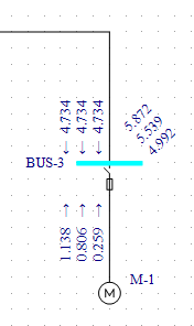
Figure 3: Initial, 0.05s and 0.25s Currents
Asymmetrical Faults
The currents calculated to this point have been 3-phase fault currents. EasyPower also calculates asymmetrical faults.
According to convention, single line-to-ground fault calculations assume the A-phase is faulted. For double line-to-ground and
line-to-line faults, the convention is to fault phases B and C.
Single Line-to-Ground Faults
- Click
 Line to Ground. The green dot represents ground fault. When this button is selected, all
subsequent faults will be single line-to-ground faults.
Line to Ground. The green dot represents ground fault. When this button is selected, all
subsequent faults will be single line-to-ground faults.
- Click only
Initial. The currents will show zero (see figure below). This is because the transformer (delta-delta connection
type) and motor are not grounded. By default, EasyPower displays A-phase currents.
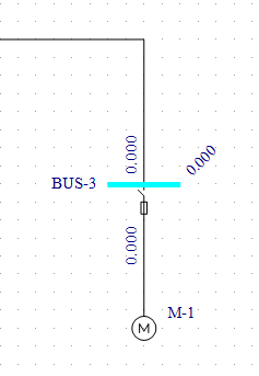
Figure 4: Single Line-to-Ground Fault
Double Line-to-Ground Faults
- Click
 Double Line to Ground. The green dots represents ground fault.
- A message will appear. Answer
Yes to fault the B-phase line rather than the A-phase. All faults will now be double line-to-ground faults.
- Double-click on BUS-3 again. The B-phase double line-to-ground fault currents are displayed (see figure below).
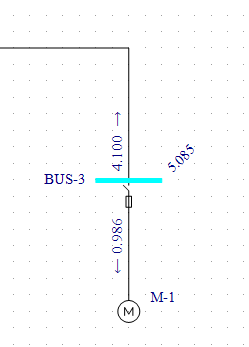
Figure 5: Double Line-to-Ground Fault
Line-to-Line Faults
- Click
 Line to Line. Yellow dots represent phase faults. Faults are now line-to-line
faults.
Line to Line. Yellow dots represent phase faults. Faults are now line-to-line
faults.
- The program displays the B-phase line-to-line fault currents (see figure below).
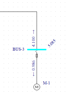
Figure 6: Line-to-Line Fault
Text Reports
- Select
 SC Reports.
- Click the Text Output tab, select the
Create Short Circuit 909 Report check box, and then click
OK.
- Click
 3-Phase. This returns you to 3-phase fault calculations.
- Click Fault Bus(es). A text report window is created. You can view this report either by
selecting
IEC 909 Short Circuit Report from the
Window button or by double-clicking on the window icon created in the lower left corner. Your text report will look
similar to that in the figure below.
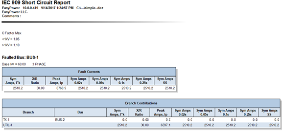
Figure 7: Short Circuit Text Report
- You can return to the one-line by selecting
Simple.dez from the
Window button.
Other Options
In the Short Circuit - IEC tab, click
 SC Options, and then click the
One-line Output tab.
SC Options, and then click the
One-line Output tab.
In this dialog box (shown below) you can also specify
Asymmetrical fault currents or
Symmetrical and
Peak currents to be displayed on the one-line. You can also show fault currents in
Per-Unit or
MVA units, and display the units.
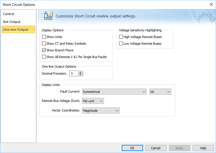
Figure 8: Short Circuit One-line Output Dialog Box.
Conclusion
This has been a brief overview of EasyPower’s short circuit analysis program. The EasyPower Help topics cover this and other features in greater
depth. To open Help, click  Help in the upper-right corner of the EasyPower window or press F1.
More Information