Orientation
Note: This topic applies to arc flash calculation methods prior to IEEE 1584-2018. With that standard, the testing was expanded to include different electrode configurations. Electrode configurations are only applicable to the IEEE 1584-2018 standard. See Electrode Configuration for more information.
Orientation describes the load side end of a conductor in relation to a worker or a block of insulation.
Vertical
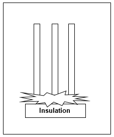
The load side end of conductor does not point towards a worker. IEEE 1584-2002, NFPA-70E (2009) and calculation methods preceding these were based on lab tests with the conductor orientation being vertical. The orientation is vertical for most equipment. In a switchgear or MCC, both the horizontal and vertical buses are considered to be “vertical” orientation if the tips of the conductors do not point outwards towards a worker.
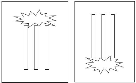
Figure 1: Examples of Vertical orientation
Horizontal
The load side end of conductor points towards a worker. Since the arc extends away from the source towards the worker, the incident energy would be higher. Arc flash tests carried out more recently had conductors in “horizontal” orientation and hence the name.
Reference: Effect of electrode orientation in arc flash testing, Wilkins, R.; Allison, M.; Lang, M., Industry Applications Conference, 2005, Volume 1, Issue 2-6 Oct. 2005 Page(s): 459 - 465 Vol. 1.
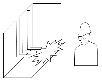
Figure 2: Example of Horizontal Orientation
Vertical into Barrier
The load side end of conductors has a block of insulation (perpendicular to the conductors). This is not the same as interphase barriers. See figure below. The insulation holds the arc in position (not allowing the arc to move away from conductors as in the case of open air). This results in higher incident energy.
Reference: Effect of Insulating Barriers in Arc Flash Testing, R. Wilkins, M. Lang and M. Allison, September 2006, Ferraz Shawmut, Inc.