Current Transformer (CT) Data
This dialog box includes the following areas and tabs:
See Common Tabs for information on the Location, Reliability, Comments, Hyperlinks, Media Gallery, or Collected Data tabs.
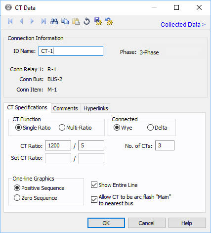
Figure 1: CT Data Dialog Box
Connection Information
| Option | Description |
|---|---|
| ID Name |
Uniquely identifies the equipment item. The program automatically assigns a name, but you can change it, if needed. The name can be up to 16 characters long. For current transformers, the program automatically assigns the names CT-1, CT-2, CT-3, and so on. |
| Conn Relay | The relay connected to the current transformer. The ID name of the connected relay is displayed here. |
| Conn Bus | The bus connected to the current transformer. The ID name of the connected bus is displayed here. |
| Conn Item | The item connected to the current transformer. The ID Name of the connected item is displayed here. |
| Group Name/Type | If the CT is part of a functional group, the group name and type appears here. See Functional Groups. |
|
Phase |
The phase of the item. Currently, this is for reference only.
|
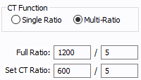
CT Specifications Tab


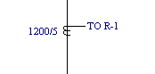
Tip: To change polarity on a CT after it has been added to the one-line, hold the SHIFT key and drag the leader line closest to the CT downward. The CT and relay must be slightly offset for this to work.

Other Tabs
See Common Tabs for information on the Location, Reliability, Comments, Hyperlinks, Media Gallery, or Collected Data tabs.
More Information
| Database Technical Reference | Common Tabs |
| Media Gallery |