Filter Data
A filter is a passive tuned circuit that presents a low impedance “sink” to currents at a given frequency or frequencies.  Filter on the Equipment Palette inserts a filter in the one-line diagram. The application of harmonic filters can cause the creation of parallel resonance below the filter tuning point (single tuned notch). The filter must be designed to minimize the impact of this resonant point.
This dialog box includes the following areas and tabs:
See Common Tabs for information on the Location, Reliability, Comments, Hyperlinks, Media Gallery, or Collected Data tabs.
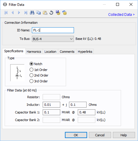
Figure 1: Filter Data Dialog Box
Connection Information
| Option | Description |
|---|---|
| ID Name |
Uniquely identifies the equipment item. The program automatically assigns a name, but you can change it, if needed. The name can be up to 16 characters long. For filters, the program automatically assigns the names FL-1, FL-2, FL-3, and so on. |
| To Bus | This is the ID name of the bus to which the equipment is connected. The base kV of the bus is indicated on the right. |
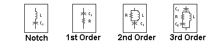
Specifications Tab
Harmonics Tab
Use the Harmonics tab to indicate whether this equipment item is introducing harmonics into your power system.
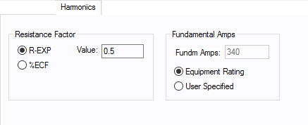
Figure 3: Harmonics Tab
| Option | Description | |||||||||||||||||||||
|---|---|---|---|---|---|---|---|---|---|---|---|---|---|---|---|---|---|---|---|---|---|---|
| Resistance Factor |
EasyPower offers two methods for calculating RH:
RH = RFund * H R-EXP RH = RFund * (1+ECF*H2)/(1+ECF) EasyPower defaults all skin effect correction to R-EXP and a value of 0.5.
|
|||||||||||||||||||||
| Fundamental Amps |
Use to set the fundamental amps. The options are as follows:
To use fundamental current calculated by power flow, select Calculated from Power Flow in the Summation Fundamental Voltage area of the Harmonics Options > Control dialog box. |
Other Tabs
See Common Tabs for information on the Location, Reliability, Comments, Hyperlinks, Media Gallery, or Collected Data tabs.
More Information
| Database Technical Reference | Common Tabs |
| Media Gallery |