Generator Data
This dialog box includes the following areas and tabs:
- Database Dialog Box Toolbar
- Connection Information
- Specifications Tab
- Power Flow Tab
- Impedance Tab
- TCC Tab
- Harmonics Tab
- Stability 1 Tab
- Stability 2 Tab
See Common Tabs for information on the Location, Reliability, Comments, Hyperlinks, Media Gallery, or Collected Data tabs.
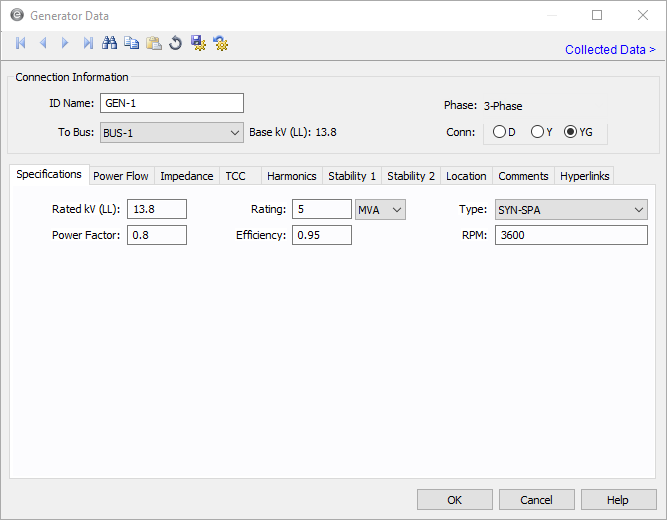
Figure 1: Generator Data Dialog Box
Connection Information


Specifications Tab
DC Generator Specifications Tab
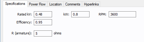
Figure 3: DC Generator Specifications Tab
| Option | Description |
|---|---|
| Rated kV | Name plate rated voltage in kV. |
| kW | Name plate (rated) power in kW. |
| RPM | Rated speed in revolutions per minute. |
| Efficiency | Efficiency in per unit. |
| R (armature) | Internal resistance of the DC generator in ohms. |
Power Flow Tab
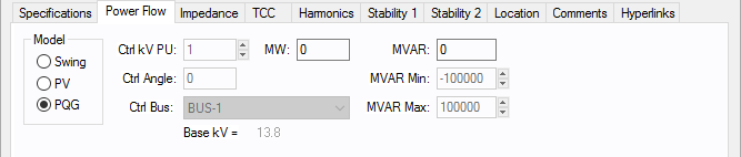
Figure 4: Power Flow tab of Generator Data Dialog Box
| Option | Description |
|---|---|
| Model |
Generator bus type used in modeling the power flow simulation. When you select a particular model, those fields that do not apply become unavailable.
|
| Ctl kV PU | Desired control voltage for a regulated generator (PV). The generator will try to control the voltage at the controlled bus to a given value. If the generator bus is the swing bus, this voltage serves as the reference voltage. The voltage is entered in per-unit. |
| Ctl Angle | Controlled angle is used only when a generator is designated as a swing bus. The value is entered in degrees. |
| Ctrl Bus |
For a PV generator (regulated), the bus that is to be controlled to the control voltage. If this field is blank in the database, EasyPower fills it in with the name of the bus listed in the To Bus field. (Note that this does not take effect until you accept it by clicking OK to close the database dialog box.) This field is ignored if the Model is set to Swing. |
| MW | Generator output MW. This may be actual operating or a rated value. This applies only to a PV or PQG generator. |
| MVAR | Generator output MVAR. This is only used when the generator is a constant power, constant var (PQG) machine or when a PV generator MVAR limit has been reached and the machine automatically switches to PQG. |
| MVAR Limits | Minimum and maximum MVAR limits for regulated generators (PV). The generator will switch to type PQG if these limits are violated. If there is only one swing generator (Model = “Swing”) on a bus, it should not have any MVAR limits. If there are more than one swing generators on a bus, at least one of them must be unlimited. |
DC Generator Power Flow Tab
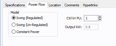
Figure 5: DC Generator Power Flow tab
| Option | Description |
|---|---|
| Model |
DC generators have three control modes:
|
|
Ctrl kV PU |
This is the scheduled per-unit voltage that the voltage control unit will try to maintain for the generator. This applies only to the Swing (Regulated) model. |
|
Output kW |
This is the scheduled output kW value that the generator will deliver to the system. This is applicable only to Constant Power. |
Impedance Tab
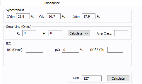
Figure 6: Impedance Tab of Generator Data Dialog Box
TCC Tab
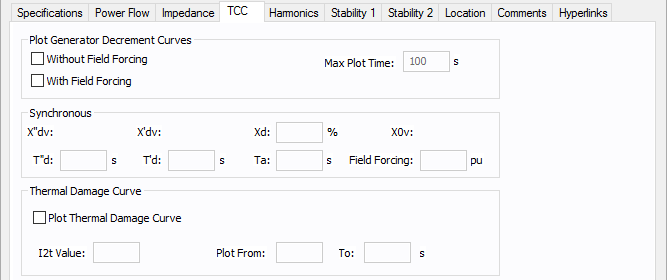
Figure 7: TCC tab of Generator Data dialog
| Option | Description |
|---|---|
| Plot Generator Decrement Curves |
You can plot short circuit decrement curves “with” and “without” excitation field forcing for comparison purposes.
|
| Synchronous | |
| Xd | Synchronous reactance of the generator, expressed as a percent. |
| T”d | Direct axis sub-transient short circuit time constant. |
| T’d | Direct axis transient short circuit time constant in seconds. |
| Ta |
Armature time constant in seconds. A typical generator datasheet will provide the Ta value. However, some manufacturers may not provide Ta in the datasheet. The armature time constant is associated with the rate of change of dc current in the stator when the generator is subjected to a 3-phase fault. Ta for different types of generators is provided in the book “Power System Control and Stability,” by Paul M. Anderson and A. A. Fouad, IEEE Press, 1994. Ta = (Ld’ + Lq) / 2r Where Ld’ is the d axis transient inductance and Lq is q axis inductance. A typical value of Ta is 0.15 seconds for fault on the machine terminal. Prabha Kundur’s book “Power System Stability and Control”, McGraw-Hill, 1994, provides the following equation for Ta: Ta = (Ld” + Lq”) / 2/ Ra Typical value for Ta lies between 0.03 and 0.35s. |
| Field Forcing |
Forced excitation current at a given load expressed as per unit value of field current at no load, Ifd0. |
|
Thermal Damage Curve This section allows you to plot “I^2t” thermal damage curve for the generator. |
|
| Plot Thermal Damage Curve | Select this check box to enable plotting of the damage curve and to enter data for this section. |
| I2t Value | This defines the (I^2)t line for the damage curve. I is in per-unit of generator rated current and t is in seconds. If I2t Value is 20, then the extrapolated damage curve line would intersect with the FLA of the generator at 20 seconds. |
| Plot From/To | The damage curve is drawn on the TCC plot within these values as the lower and upper limits in seconds. |
Harmonics Tab
Use the Harmonics tab to indicate whether this equipment item is introducing harmonics into your power system.
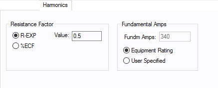
Figure 8: Harmonics Tab
| Option | Description | |||||||||||||||||||||
|---|---|---|---|---|---|---|---|---|---|---|---|---|---|---|---|---|---|---|---|---|---|---|
| Resistance Factor |
EasyPower offers two methods for calculating RH:
RH = RFund * H R-EXP RH = RFund * (1+ECF*H2)/(1+ECF) EasyPower defaults all skin effect correction to R-EXP and a value of 0.5.
|
|||||||||||||||||||||
| Fundamental Amps |
Use to set the fundamental amps. The options are as follows:
To use fundamental current calculated by power flow, select Calculated from Power Flow in the Summation Fundamental Voltage area of the Harmonics Options > Control dialog box. |
Stability 1 Tab
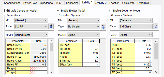
Figure 9: Stability 1 Tab
Generator Model
| Option | Description |
|---|---|
| Enable Generator Model | Select the check box to enter stability information. |
| Mfr | Provides a list of manufacturers available in the device library. If the desired manufacturer is not listed in the device library, you can add it to the library. |
| Type | Equipment types available from the selected manufacturer. If the desired type is not listed, you can add it to the library. |
| Model | Equipment models available from the selected equipment type. If the desired model is not listed, you can add it to the library. |
 Lib Lib |
Populates the table with equipment data from the library. See EasyPower Device Library for more information. |
Exciter Model
| Option | Description |
|---|---|
| Enable Exciter Model | Select the check box to enter stability information. |
| Mfr | Provides a list of manufacturers available in the device library. If the desired manufacturer is not listed in the device library, you can add it to the library. |
| Type | Equipment types available from the selected manufacturer. If the desired type is not listed, you can add it to the library. |
| Model | Equipment models available from the selected equipment type. If the desired model is not listed, you can add it to the library. |
|
Lib |
Populates the table with equipment data from the library. See EasyPower Device Library for more information. |
Governor Model
| Option | Description |
|---|---|
| Enable Governor Model | Select the check box to enter stability information. |
| Mfr | Provides a list of manufacturers available in the device library. If the desired manufacturer is not listed in the device library, you can add it to the library. |
| Type | Equipment types available from the selected manufacturer. If the desired type is not listed, you can add it to the library. |
| Model | Equipment models available from the selected equipment type. If the desired model is not listed, you can add it to the library. |
|
Lib |
Populates the table with equipment data from the library. See EasyPower Device Library for more information. |
For details on the parameters, see Dynamic Stability . For information about the library, see EasyPower Device Library.
Stability 2 Tab
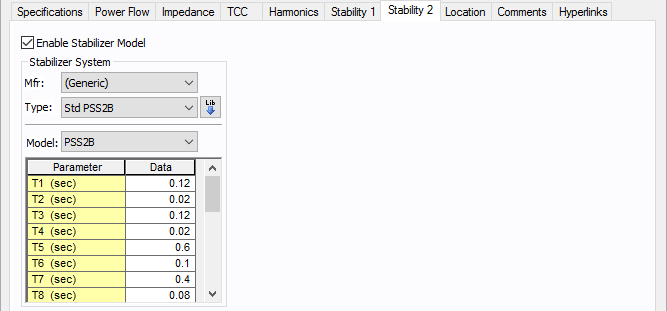
Figure 10: Stability 2 Tab
Stabilizer Model
| Option | Description |
|---|---|
| Enable Stabilizer Model | Select the check box to enter stability information. |
| Mfr | Provides a list of manufacturers available in the device library. If the desired manufacturer is not listed in the device library, you can add it to the library. |
| Type | Equipment types available from the selected manufacturer. If the desired type is not listed, you can add it to the library. |
| Model | Equipment models available from the selected equipment type. If the desired model is not listed, you can add it to the library. |
|
Lib |
Populates the table with equipment data from the library. See EasyPower Device Library for more information. |
For details on the parameters, see Dynamic Stability . For information about the library, see EasyPower Device Library.
Other Tabs
See Common Tabs for information on the Location, Reliability, Comments, Hyperlinks, Media Gallery, or Collected Data tabs.
More Information
| Database Technical Reference | Common Tabs |
| Media Gallery |