Inverter Data
This dialog box includes the following areas and tabs:
- Database Dialog Box Toolbar
- Connection Information
- Specifications Tab
- Power Flow Tab
- Harmonics Tab
- Stability Tab
See Common Tabs for information on the Location, Reliability, Comments, Hyperlinks, Media Gallery, or Collected Data tabs.
See also Notes on Inverter Model.
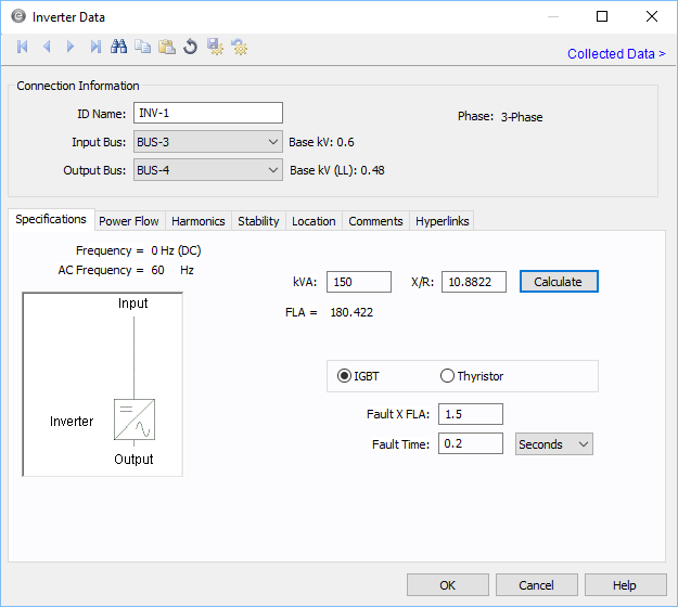
Figure 1: Inverter Data Dialog Box
Connection Information
Specifications Tab
| Option | Description |
|---|---|
| kVA | Rated output kVA of the inverter. |
| X/R | X/R ratio of the inverter short circuit contribution as seen from the load side. |
| IGBT / Thyristor | Type of inverter. This affects power flow simulation methods. If IGBT, there are three control modes possible. For Thyristor, the output real and reactive power conditions are simulated using Kimbark’s equations. |
| Fault x FLA | Maximum fault current expected on the load side in multiples of the full load amps (FLA) rating. |
| Fault Time | Duration the inverter can supply the fault current. The time can be specified in cycles or seconds. |
Power Flow Tab
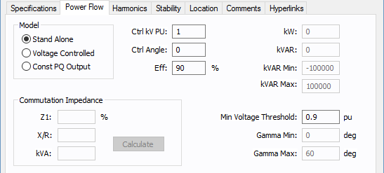
Figure 2: Power Flow tab of the Inverter Dialog Box
| Option | Description |
|---|---|
| Model |
Describes the way the output of the inverter is controlled for IGBT type. The options are:
|
| Ctrl kV PU | The per unit magnitude of Inverter output voltage. This is maintained at the specified value for a Stand Alone model, and is maintained at the specified value while within var limits for a Voltage Controlled model. |
| Ctrl Angle | The angle in degrees of the controlled output voltage for Stand Alone model. |
| Eff | Efficiency of the inverter. This is the ratio between output and input power in percent. |
| kW | Specified controlled output active power in kW for Voltage Controlled and Const PQ Output models. |
| kVAR | Specified controlled output reactive power in kVAR for Const PQ Output models. |
| kVAR Min | Minimum kVAR capability of the inverter in voltage controlled mode. |
| kVAR Max | Maximum kVAR capability of the inverter in voltage controlled mode. |
| Min Voltage Threshold |
For an IGBT inverter only, if the DC voltage on the input to the inverter drops below this value, then the inverter begins stepping its specified kW loading down until the input voltage rises above Min Voltage Threshold. Note: The power flow will not solve when loading on photovoltaics causes them to experience a severe terminal under-voltage. Therefore, this special control was added so that inverters fed by photovoltaics reduce load when voltage drops below VMP so that photovoltaics are required to supply less power, thus helping the DC voltage on the photovoltaics increase into a range where a power flow solution can be reached. |
| Gamma Min | Minimum inverter margin angle in degrees for thyristor type inverter. |
| Gamma Max | Maximum inverter margin angle in degrees for thyristor type inverter. |
| Commutation Impedance |
Commutation impedance used to calculate the power flow using Kimbark’s equations with Thyristor type. The inverter must feed a dedicated transformer that matches these same values one-for-one.
|
Harmonics Tab
Use the Harmonics tab to indicate whether this equipment item is introducing harmonics into your power system.
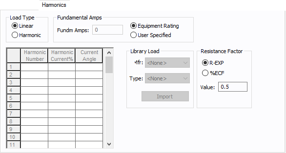
Figure 3: Harmonics Tab
| Option | Description | |||||||||||||||||||||
|---|---|---|---|---|---|---|---|---|---|---|---|---|---|---|---|---|---|---|---|---|---|---|
| Load Type |
The default is Linear, indicating the equipment does not produce harmonics. Choosing Harmonic makes the item an harmonic source and makes other fields in this tab available to edit. Note: For an adjustable frequency drive (AFD), the Load Type is always Harmonic. |
|||||||||||||||||||||
| Fundamental Amps |
Use to set the fundamental amps. The options are as follows:
To use fundamental current calculated by power flow, select Calculated from Power Flow in the Summation Fundamental Voltage area of the Harmonics Options > Control dialog box. |
|||||||||||||||||||||
| Harmonic Spreadsheet |
Use the spreadsheet to enter the harmonic spectrum produced by this item. You can enter up to 30 different harmonics in each equipment item. In the spreadsheet, enter the Harmonic Number (such as 5 for the 5th harmonic), the Harmonic Current in percent of the Fundamental Amps, and the Current Angle. By indicating the current angle, you can simulate transformer phase shift effects on rectifiers so appropriate canceling can take place. The harmonic may be integer or non-integer. |
|||||||||||||||||||||
| Library Load |
Common harmonic spectra may be entered from the device library. For instructions on how to enter your own spectra information, see Harmonics with Spectrum™. After selecting a particular device library spectrum from the Mfr and Type lists, click Import, and that spectrum is entered into the harmonic spreadsheet. |
|||||||||||||||||||||
| Resistance Factor |
EasyPower offers two methods for calculating RH:
RH = RFund * H R-EXP RH = RFund * (1+ECF*H2)/(1+ECF) EasyPower defaults all skin effect correction to R-EXP and a value of 0.5.
|
Stability Tab
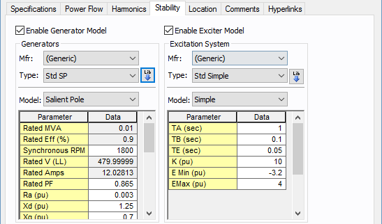
Figure 4: Stability Tab
Generator Model
| Option | Description |
|---|---|
| Enable Generator Model | Select the check box to enter stability information. |
| Mfr | Provides a list of manufacturers available in the device library. If the desired manufacturer is not listed in the device library, you can add it to the library. |
| Type | Equipment types available from the selected manufacturer. If the desired type is not listed, you can add it to the library. |
| Model | Equipment models available from the selected equipment type. If the desired model is not listed, you can add it to the library. |
 Lib Lib |
Populates the table with equipment data from the library. See EasyPower Device Library for more information. |
Exciter Model
| Option | Description |
|---|---|
| Enable Exciter Model | Select the check box to enter stability information. |
| Mfr | Provides a list of manufacturers available in the device library. If the desired manufacturer is not listed in the device library, you can add it to the library. |
| Type | Equipment types available from the selected manufacturer. If the desired type is not listed, you can add it to the library. |
| Model | Equipment models available from the selected equipment type. If the desired model is not listed, you can add it to the library. |
|
Lib |
Populates the table with equipment data from the library. See EasyPower Device Library for more information. |
Other Tabs
See Common Tabs for information on the Location, Reliability, Comments, Hyperlinks, Media Gallery, or Collected Data tabs.
More Information
| Database Technical Reference | Common Tabs |
| Notes on Inverter Model | |
| Media Gallery |