Load Data
This dialog box includes the following areas and tabs:
See Common Tabs for information on the Location, Reliability, Comments, Hyperlinks, Media Gallery, or Collected Data tabs.
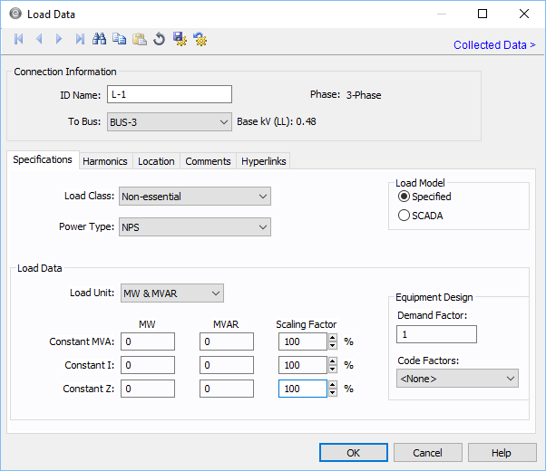
Figure 1: Load Data Dialog Box
Connection Information
Specifications Tab
| Option | Description |
|---|---|
| Load Class | To specify the class of in terms of importance. You can select Essential, Critical, or Non-essential. This field does not affect analysis. It can be used in database query to distinguish a certain load class from others. See Advanced Query. |
| Load Model |
Specified: Designates the Load Data field to a user-entered model. You can enter any combination of constant kVA, constant I, or constant Z load. SCADA: Designates the Load Data field to an imported real-time SCADA model. Data can also be user input in the SCADA fields just like Specified data. |
|
Power Type |
Select the power type for the equipment. The options are:
|
|
Load Data Any combination of constant kVA, constant current, or constant impedance loads may be modeled. Different types of loads can also be mixed and matched to model a specific type of equipment such as variable speed drives. |
|
| Load Unit | Specifies the units that will be used for load data. Use the box to choose the unit. |
| Constant kVA/MVA | Constant kVA load entered in MW and MVAR. Note that the term “constant kVA” seems to be an industry standard even though MVA seems to be the more common unit for large industrial uses. See also Notes on Power Factor. |
| Constant I | Constant current load given in MW and MVAR. These values should be entered in per-unit. |
| Constant Z | Constant impedance load given in MW and MVAR. These values should be entered in per-unit. |
| Scaling Factor | Each load can be varied by applying a different scaling factor. This lets you model the actual panel or lumped load on a bus, then study different loading conditions. This allows quick “what if” studies and prevents errors that occur from data entry. |
| Demand Factor | Demand factor for the load. |
| Code Factors | NEC code factor for the load. |
DC Load Specifications
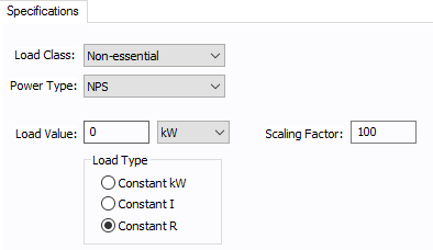
Figure 2: DC Load Specifications
Harmonics Tab
Use the Harmonics tab to indicate whether this equipment item is introducing harmonics into your power system.
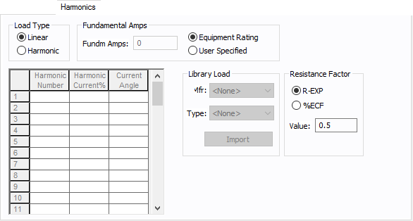
Figure 3: Harmonics Tab
| Option | Description | |||||||||||||||||||||
|---|---|---|---|---|---|---|---|---|---|---|---|---|---|---|---|---|---|---|---|---|---|---|
| Load Type |
The default is Linear, indicating the equipment does not produce harmonics. Choosing Harmonic makes the item an harmonic source and makes other fields in this tab available to edit. Note: For an adjustable frequency drive (AFD), the Load Type is always Harmonic. |
|||||||||||||||||||||
| Fundamental Amps |
Use to set the fundamental amps. The options are as follows:
To use fundamental current calculated by power flow, select Calculated from Power Flow in the Summation Fundamental Voltage area of the Harmonics Options > Control dialog box. |
|||||||||||||||||||||
| Harmonic Spreadsheet |
Use the spreadsheet to enter the harmonic spectrum produced by this item. You can enter up to 30 different harmonics in each equipment item. In the spreadsheet, enter the Harmonic Number (such as 5 for the 5th harmonic), the Harmonic Current in percent of the Fundamental Amps, and the Current Angle. By indicating the current angle, you can simulate transformer phase shift effects on rectifiers so appropriate canceling can take place. The harmonic may be integer or non-integer. |
|||||||||||||||||||||
| Library Load |
Common harmonic spectra may be entered from the device library. For instructions on how to enter your own spectra information, see Harmonics with Spectrum™. After selecting a particular device library spectrum from the Mfr and Type lists, click Import, and that spectrum is entered into the harmonic spreadsheet. |
|||||||||||||||||||||
| Resistance Factor |
EasyPower offers two methods for calculating RH:
RH = RFund * H R-EXP RH = RFund * (1+ECF*H2)/(1+ECF) EasyPower defaults all skin effect correction to R-EXP and a value of 0.5.
|
Other Tabs
See Common Tabs for information on the Location, Reliability, Comments, Hyperlinks, Media Gallery, or Collected Data tabs.
More Information
| Database Technical Reference | Common Tabs |
| Notes on Power Factor | |
| Media Gallery |