Low Voltage Breaker Data
This dialog box includes the following areas and tabs:
See Common Tabs for information on the Location, Reliability, Comments, Hyperlinks, Media Gallery, or Collected Data tabs.
Note: DC LV breakers are modeled similar to AC breakers. Only molded case thermal magnetic circuit breakers are currently supported for DC. Enter data in the Specifications tab and Phase Trip tab. For fused breakers, you can enter additional fuse data in the Fuse tab.
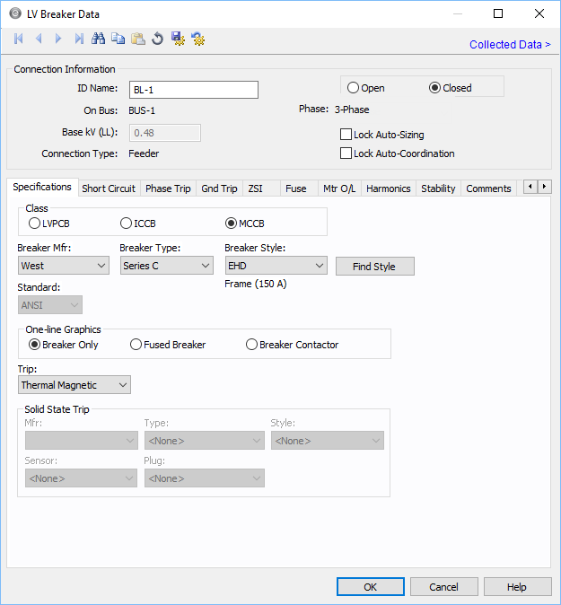
Figure 1: Low Voltage Breaker Data Dialog Box
Connection Information
| Option |
Description |
| ID Name |
Uniquely identifies the equipment item. The program automatically assigns a name, but you can change it, if needed. The name can be up to 16 characters long.
For low voltage breakers, the program automatically assigns the names BL-1, BL-2, BL-3, and so on.
|
| On Bus |
The bus connected to the low voltage breaker, which must already exist on the one-line. Next to the bus name, the Base kV of the bus is displayed.
|
|
Phase
|
The phase of the item. Currently, this is for reference only.
|
| Connection Type |
If the low voltage breaker is connected to two buses, then the connection type is Bus Tie. For all other connections, the connection type is Feeder. |
| Open |
Normal state of the low voltage breaker. If Open is selected, the one-line displays OPEN next to the low voltage breaker symbol. |
| Closed |
Normal state of the low voltage breaker. If Closed is selected, the one-line does not display text next to the low voltage breaker symbol. |
| Lock Auto-Sizing |
When this check box is selected, this item cannot be automatically sized using SmartDesign™ (the auto-design feature). |
| Lock Auto-Coordination |
When this check box selected, this item cannot be automatically sized using SmartPDC™ (the auto-coordination feature). |
Specifications Tab
| Option |
Description |
| Class |
Low voltage breakers are separated into three categories:
- LVPCB: Low voltage power circuit breakers
- ICCB: Insulated case circuit breakers
- MCCB: Molded case circuit breakers
These classes of breakers are each listed separately in the equipment field of the device library. Depending upon the class of breaker you select, the list of manufacturers for the breaker class will be available in the Breaker Mfr box.
|
| Breaker Mfr |
Provides a list of manufacturers available in the device library. If the desired manufacturer is not listed in the device library, you can add it to the library.
The list of manufacturers shown depends on the class of breaker. Select the class before selecting manufacturer.
|
| Breaker Type |
Equipment types available from the selected manufacturer. If the desired type is not listed, you can add it to the library.
A type would include a group of models or brands with similar functions.
|
| Breaker Style |
Low voltage breaker styles available from the manufacturer for the type chosen above. Styles are essentially models. Breaker frame size for selected style will appear under breaker style field. |
| Standard |
Displays whether the selected breaker is ANSI or IEC. |
| One-line Graphics |
Select the symbol you want to see on the one-line:
- Breaker Only: LV breaker..........

- Fused Breaker: Fused LV breaker..........

- Breaker Contactor: LV breaker with a contactor...........

|
| Trip |
Type of trip device or mechanism. Selecting the type of trip device affects the contents of the dialog box.
- For LVPCB class, you can select Solid State Trip or Non-Solid State Trip.
- For ICCB and MCCB classes, you can select Solid State Trip or Thermal Magnetic.
|
| Solid State/Non-Solid State Trip This section is available for selection only when Solid State Trip or Non-Solid State Trip is selected in the Trip field. |
| Mfr |
Provides a list of manufacturers available in the device library. If the desired manufacturer is not listed in the device library, you can add it to the library. |
| Type |
Equipment types available from the selected manufacturer. If the desired type is not listed, you can add it to the library. |
| Style |
Trip unit styles (or models) available from the manufacturer for the type chosen above. |
| Sensor |
(Solid state trip only) Sensor rating of the trip unit for the style chosen above. The sensor feeds the trip unit with a current proportional to the current in circuit. Selected sensor value may be used in calculation to plot TCC. |
| Plug / Tap |
(Solid state trip only) The plug or tap values available for the sensor selected. Selected plug or tap value may be used to determine trip pickup. Either the Plug or Tap field appears, depending on the data entered in the library. |
Short Circuit Tab
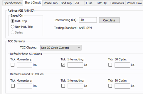
Figure 2: Short Circuit Dialog Box (ANSI)
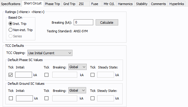
Figure 3: Short Circuit Dialog Box (IEC)
| Option |
Description |
| Ratings Based On |
In many cases, the type of trip or the application of the breaker determines the interrupting current of the breaker. Older (pre-1964) low voltage power circuit breakers with instantaneous trips typically have higher interrupting ratings than the same device without instantaneous trips. The LVPCB device library allows instantaneous and non-instantaneous trip ratings. All ICCB and MCCB breakers are equipped with instantaneous trips. The old cascade application for LVPCBs is not supported in this library. However, you can determine this rating and enter the value directly into the Interrupting kA field.
Recent standards allow ICCBs and MCCBs to be rated for series application. This provides increased interrupting kA for some devices. The ICCB and MCCB device libraries allow instantaneous and series rated trip ratings.
|
| Interrupting/Breaking (kA) |
The interrupting rating of the breaker (for ANSI) or breaking rating (for IEC). |
| Calculate |
Fills in a computed value for the Interrupting kA field, based on the device library entry for Mfr, Type, Style and the base kV. (The Interrupting kA value is based on the breaker multi-pole rating at the 480 volt level.) You can override interrupting kA by typing in different numbers. This button also causes the appropriate Testing Standard to be displayed for your information. (The Testing Standard comes directly from the device library and cannot be changed.)
Calculation of series ratings: When you calculate the Interrupting kA based on Series Rating, you will first need to define the upstream breaker Mfr, Type and Style. If the library has the series rating data, then the data is imported from the library. If not, the fully rated instantaneous trip value is used.
|
| Testing Standard |
The standard to which the device complies for testing procedure. |
| TCC Defaults |
Data entered in this section is used to place tick marks representing short circuit values on the TCC plot. |
| TCC Clipping |
You can clip the time current curve (TCC) for the breaker at the specified current in kA for Momentary (1/2 cycle), 5-cycle or 30-cycle for ANSI or Initial, Breaking, or Steady State for IEC. Select <None> to avoid clipping of TCC. |
| SC Tick Marks |
Select the appropriate boxes to display the tick mark on the TCC plot.
- ANSI: You can display momentary, interrupting, and 30 cycle short circuit values.
- IEC: You can display initial, breaking, and steady state short circuit values. If you select to display breaking values, you can also specify to use a global value or select from a specific value including .02, .05, 0.1, or > 0.25. The global value is set in Short Circuit Options on the Control tab under IEC-60909 Settings.
Enter the corresponding short circuit values in kA in their respective edit fields for phase short circuit and ground short circuit.
|
| Default Phase SC Values |
The values in kA, entered in these fields can be displayed for phase currents on TCC plots. |
| Default Ground SC Values |
The values in kA, entered in these fields can be displayed for ground currents on TCC plots. Ground SC values section is applicable only for solid state trip units with ground fault trip. |
Phase Trip Tab
The Phase Trip tab stores data which determine the TCC curves of the device for phase currents. Pickup and delay settings for long time, thermal, short time, and instantaneous trip of the device are selected here. The fields and contents that appear on the dialog box depend upon the type of trip unit selected on the Specification tab.
Phase Trip for Thermal Magnetic
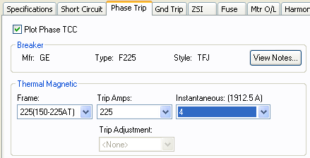
Figure 4: Phase Trip Dialog Box for Thermal Magnetic
| Option |
Description |
| Plot Phase TCC |
This option is only available after you set the Trip and Solid State Trip fields on the Specifications tab.
You can also select or clear it in the Temporary Thermal Magnetic Data dialog box in Coordination mode to avoid plotting the TCC.
|
| Breaker |
This message shows the manufacturer (Mfr), Type and Style of low voltage breaker that was selected. |
| View Notes |
Click to view notes recorded in the library for the device. Information may include data sheets or manufacturer's information for the device or assumptions needed to model the device.
|
| Frame |
Frame description. This may be the frame size, the largest rating in the range of similar models, or a range of sizes that have similar curves. |
| Trip Settings |
Nominal rated amps the device is rated to carry without tripping. |
| Instantaneous |
Nominal instantaneous trip amps, multiple, or pickup setting. When you highlight or select a choice, the corresponding trip amps appear in parenthesis. |
Phase Trip for Solid State Trip
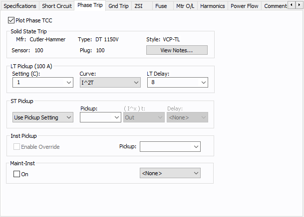
Figure 5: Phase Trip dialog box for Solid State Trip
| Option |
Description |
| Plot Phase TCC |
For solid state trip devices, this field can be selected to plot TCC or cleared to avoid plotting the TCC of the phase trip characteristics. To obtain a TCC plot of a Ground Trip only, clear this check box. |
| Solid State Trip |
This section shows the kind of trip unit selected and other descriptions of device selected in the Specifications tab such as the manufacturer (Mfr), Type, Style, Sensor rating, and Plug/Trip value of the trip unit. |
| View Notes |
Click to view notes recorded in the library for the device. Information may include data sheets or manufacturer's information for the device or assumptions needed to model the device. |
| LT Pickup |
The long time pickup and delay are selected in this section. The pickup calculation depends on the device selected. It may include LTPU Mult, but it will include Setting (C) and either Sensor or Plug/Tap. After the settings are selected, the actual pickup in amperes appears in parentheses.
-
Setting (C): The long time pickup current setting below which the device will not trip. This is a fraction of the sensor or plug/tap amps. For some trip units LTPU multiple may also be required to set the pickup current.
LTPU Mult: Multiple of Setting (C), which can be adjusted to “fine-tune” the long time pickup setting. Some trip units may not have this feature.
Curve: Some solid state curves may have multiple LT delay curves to choose from. This field enables you to choose the curve shape.
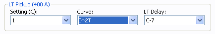
Figure 6: LT Delay Curve
-
LT Delay: Long time delay setting to select the delay band.
|
| ST Pickup |
Short time pickup and delay settings. This section is applicable to only devices with short time trip. After the settings are selected, the actual pickup in amperes appears in parentheses.
- Pickup: The short time pickup current setting below which the device will not trip for short time trip. The short time pickup setting may be a multiple of long time pickup, sensor rating, plug or tap value, or the current setting times the sensor or plug/tap.
- (I^x)t: To select shape and slope of delay short time band. When you select In, the (I^x)t function is enabled. The delay band has a slope of minus “x”. When you select Out, the (I^x)t function is unavailable, and the short time delay is independent of the current. For some new circuit breakers, the (I^x)t delay may be adjustable. In such cases, the choices available will be the various possible delay settings.
- Delay: Short time delay setting to select the delay band.
|
| Inst Pickup |
Nominal instantaneous trip amps, multiple, or pickup setting. When you highlight or select a choice, the corresponding trip amps appear in parenthesis.
- Enable Override: Selecting this option disables tripping based on pickup setting. The device trips at an override value that depends on the device style. This feature may or may not be applicable to the device selected.
- Pickup: The instantaneous trip pickup setting.
|
| Maint-Inst |
This is the additional instantaneous setting used during maintenance to lower the arc flash hazard. The name of this section may be manufacturer specific such as ARMS, Maint Mode, RELT, Quick-Trip, and so on.
- On: Of selected, this indicates the maintenance switch is on. In analysis focus, you can select the breakers and right-click to toggle the maintenance mode switch on or off.
- Pickup: Setting for maintenance mode trip.
|
Phase Trip for Non-Solid State Trip
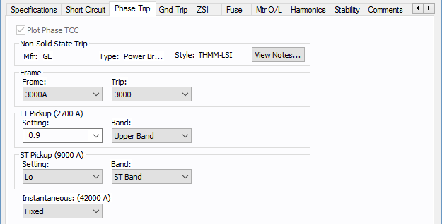
Figure 7: Phase Trip Tab for Non-Solid State Trip
| Option |
Description |
| Plot Phase TCC |
This check box is only available if the Trip and Solid State Trip settings are selected on the Specifications tab. You can also select or clear it in the Temporary Thermal Magnetic Data dialog box in coordination mode to avoid plotting the TCC. |
| Non-Solid State Trip |
This message shows the kind of trip unit selected and other descriptions of the device selected in the Specifications tab such as the manufacturer (Mfr), Type and Style of low voltage circuit breaker. |
| View Notes |
Click to view notes recorded in the library for the device. Information may include data sheets or manufacturer's information for the device or assumptions needed to model the device. |
| Frame |
Frame and Trip descriptions.
- Frame: This may be the frame size, the largest rating in the range of similar models, or a range of sizes that have similar curves.
- Trip: Nominal rated amps the breaker is rated to carry without tripping.
|
| LT Pickup |
The long time pickup and delay are selected in this section. After the settings are selected, the actual pickup in amperes appears in parentheses.
- Setting: The long time pickup setting below which the device will not trip. This is a multiple of the Trip amps or the trip unit rating.
- Band: Long time delay band to adjust the delay.
|
| ST Pickup |
Short time pickup and delay settings. This section is applicable to only devices with short time trip. After the settings are selected, the actual pickup in amperes appears in parentheses.
- Setting: The short time pickup setting below which the device will not trip for short time delay. This is a multiple of the long time pickup.
- Band: Short time delay band to adjust the delay.
|
| Instantaneous |
The instantaneous pickup setting, which is a multiple of long time pickup. When you highlight or select a choice, the corresponding trip amps appear in parenthesis. |
Ground Trip Tab
This tab section is applicable for solid state trip devices, but not for thermal magnetic and non-solid state trip devices.
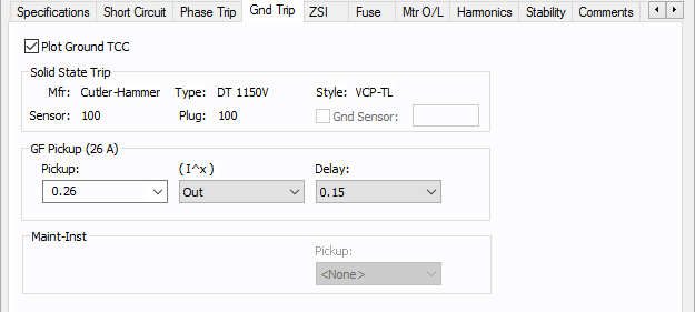
Figure 8: Ground Trip Dialog Box for Solid State Trip
| Option |
Description |
| Plot Ground TCC |
For solid state trip devices, this field can be checked to plot TCC or unchecked to avoid plotting the TCC of the ground trip characteristics. |
| Solid State Trip |
This section shows the kind of trip unit selected and other descriptions of device selected in the Specifications tab such as the manufacturer (Mfr), Type, Style, Sensor rating, and Plug/Trip value of trip unit. |
| Ground Trip |
This section is for setting the ground fault pickup, the type of delay and the delay time.
- Pickup: The ground fault pickup setting, which is either in amps or multiple of sensor, plug, or setting C.
- (I^x)t: To select shape and slope of ground fault delay band. When you select In, the (I^x)t function is enabled. The delay band has a slope of minus “x”. When you select Out, the (I^x)t function is disabled and the delay is independent of the current.
- Delay: Ground fault delay setting to select the delay band.
|
| Maint-GF |
This is the ground instantaneous setting used during maintenance to lower the arc flash hazard. The name of this section may be manufacturer specific such as ARMS, Maint Mode, RELT, Quick-Trip, etc. The On/Off switch for the maintenance mode is the check box on the Phase Trip tab.
|
| Pickup |
Setting for the maintenance mode trip for ground fault. |
ZSI Tab
The ZSI tab specifies the zone selective information for LV breakers. This information is used in coordination, fault simulations and arc flash calculations. EasyPower automatically determines the fault zone for each breaker and trips only the breakers in the fault zone. The ZSI feature is available in some breakers only and is specified in the device library.
Note: Since the ZSI information depends on other breakers, it is best to fill in ZSI information only after other data has been entered.
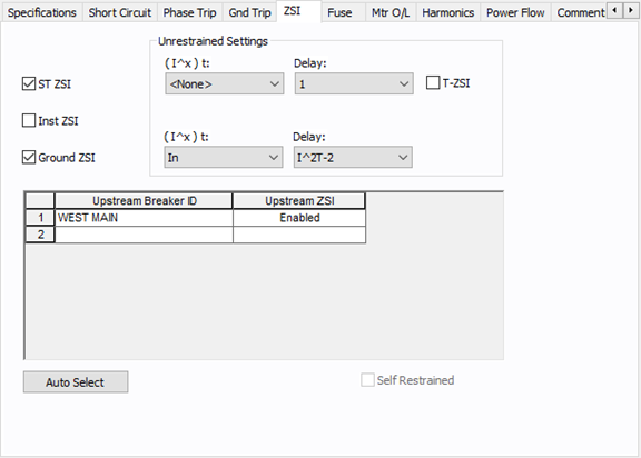
Figure 9: ZSI tab of LV Breaker Data dialog
| Option |
Description |
| ST ZSI |
Select to indicate if the Short Time Trip ZSI is set On. In analysis focus (Short Circuit, Coordination, and so on), ST ZSI can be turned “On” or “Off” temporarily using the right-click context menu.
If you select this option, you can specify the (I^x)t and delay values for the unrestrained settings for the short time ZSI curve.
|
| Inst ZSI |
Select to indicate if the Instantaneous Trip ZSI is set On. In analysis focus (Short Circuit, Coordination, and so on), Inst ZSI can be turned “On” or “Off” temporarily using the right-click context menu. |
| Ground ZSI |
Select to indicate if the Ground Trip ZSI is set On. In analysis focus (Short Circuit, Coordination, and so on), Ground ZSI can be turned “On” or “Off” temporarily using the right-click context menu.
If you select this option, you can specify the (I^x)t and delay values for the unrestrained settings for the ground ZSI curve.
|
| T-ZSI |
Select to enable the T-ZSI (threshold zone selective interlocking) mode of operation. T-ZSI is a special zone selective interlocking (ZSI) feature that is available in certain trip units manufactured by GE. In this scheme, the downstream breaker can send a restraining signal to an upstream breaker at 81% of the set short time pickup or instantaneous pickup. The upstream breaker will shift its pickup to 123% when it receives a restraining. Refer to the manufacturer's documents on the details of T-ZSI operation. |
| Upstream Breaker ID |
List of upstream breakers that receive restraining signal from this breaker. Typically, there will be one upstream breaker. All LV breakers immediately upstream, downstream or adjacent, will be available in the box. Pick the appropriate breaker. The ZSI status for the upstream breaker is indicated in the column on the right (Upstream ZSI). |
| Upstream ZSI |
This column automatically indicates whether the ZSI is On in the breaker selected in Upstream Breaker ID column. |
| Auto Select |
Command button to automatically list all the immediately upstream, downstream or adjacent breakers in the Upstream Breaker ID column. After choosing this button, you can delete the undesired breakers from the spreadsheet. |
| Self Restrained |
Self-restrained breakers have the ZSI “Out” terminals jumpered to the ZSI “In” terminals so that the breaker always trips on restrained mode. Restrained mode is typically a short time delay trip. If a breaker is self-restrained, then select this check box. If a breaker is self restrained, it allows downstream breakers without ZSI to trip. At the same time, it sends a restraining signal to an upstream breaker to enable the self restrained unit to trip first (preventing the upstream breaker to trip on instantaneous). This provides selective coordination. |
Fuse Tab
This section is applicable for fused breakers only, and the fields in this dialog box are used to select the fuse.
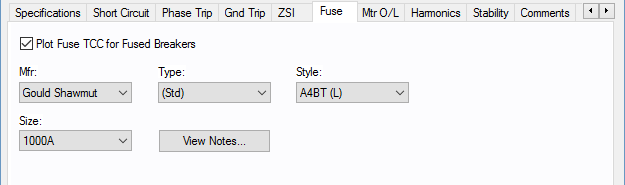
Figure 10: Fuse Dialog Box for Fused Breakers
| Option |
Description |
| Plot Fuse TCC for Fused Breakers |
For fused breakers, this field can be selected to plot TCC or cleared to avoid plotting the TCC of the fuse trip characteristics. |
| Mfr |
Provides a list of manufacturers available in the device library. If the desired manufacturer is not listed in the device library, you can add it to the library. |
| Type |
Equipment types available from the selected manufacturer. If the desired type is not listed, you can add it to the library.
|
| Style |
Low voltage fuse styles available from the manufacturer for the type chosen above.
A style may be a brand name or the name of the group of fuses with similar functions.
|
| Size |
The ampere rating of the fuse. |
| View Notes |
Click to view notes recorded in the library for the device. Information may include data sheets or manufacturer's information for the device or assumptions needed to model the device. |
Mtr O/L (Motor Overload) Tab
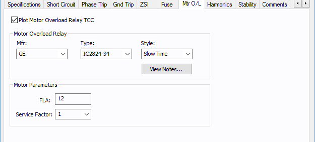
Figure 11: Motor Overload Relay Dialog Box
| Option |
Description |
| Plot Motor Overload Relay TCC |
This field can be selected to plot TCC or cleared to avoid plotting the TCC of the motor overload relay which trips the LV breaker. |
| Motor Overload Relay |
To specify the motor overload relay associated with the breaker in protecting the motor. |
| Mfr |
Provides a list of manufacturers available in the device library. If the desired manufacturer is not listed in the device library, you can add it to the library. |
| Type |
Equipment types available from the selected manufacturer. If the desired type is not listed, you can add it to the library.
|
| Style |
Motor overload relay styles available from the manufacturer for the type chosen above. |
| Motor Parameters |
Determines the pickup level for the motor overload relay. You can specify the value. |
| FLA |
The full load amps specified for motor, or the relay rating. |
| Service Factor |
Overload factor of the rated amps. This factor does not increase the rating but simply increases the pickup level. You can enter any value between 1.0 and 1.25. |
Harmonics Tab
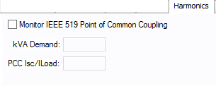
Figure 12: Harmonics Tab
| Option |
Description |
| Monitor IEEE 519 Point of Common Coupling |
EasyPower can monitor whether or not the IEEE 519 guideline for harmonics is met at the point of common coupling.
If selected, then the Harmonics Report indicates when this guideline is not being met.
|
| kVA Demand |
The kVA demand. |
| PCC Isc/Load |
The ratio of short circuit current to load current at the point of common coupling. |
Stability Tab
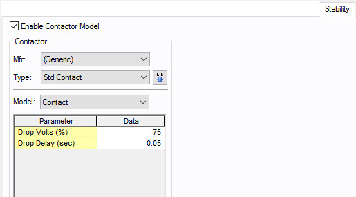
Figure 13: Stability Tab
| Option |
Description |
| Enable Contactor Model |
Select the check box to enter stability information. |
| Mfr |
Provides a list of manufacturers available in the device library. If the desired manufacturer is not listed in the device library, you can add it to the library. |
| Type |
Equipment types available from the selected manufacturer. If the desired type is not listed, you can add it to the library. |
| Model |
Equipment models available from the selected equipment type. If the desired model is not listed, you can add it to the library. |
 Lib Lib |
Populates the table with equipment data from the library. See EasyPower Device Library for more information. |
Other Tabs
See Common Tabs for information on the Location, Reliability, Comments, Hyperlinks, Media Gallery, or Collected Data tabs.
More Information