Motor Data
This dialog box includes the following areas and tabs:
- Database Dialog Box Toolbar
- Connection Information
- Specifications Tab
- DC Motor Specifications Tab
- Short Circuit Tab
- TCC Tab
- Power Flow Tab
- DC Motor Power Flow Tab
- Motor Starting Tab
- Harmonics Tab
- Stability Tab
See Common Tabs for information on the Location, Reliability, Comments, Hyperlinks, Media Gallery, or Collected Data tabs.
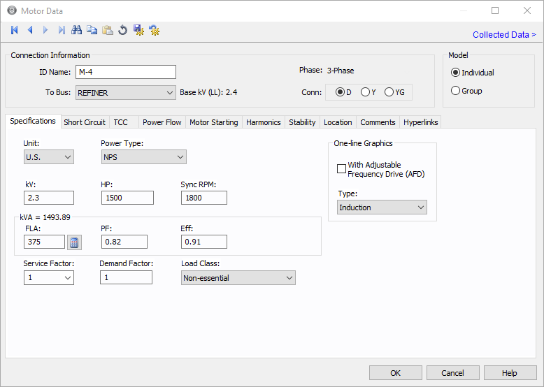
Figure 1: Motor Data Dialog Box
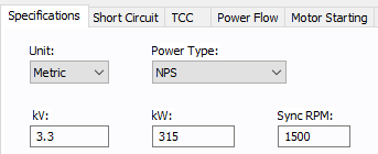
Figure 2: Motor Data Dialog Box (Metric)
Connection Information
Specifications Tab
| Option | Description |
|---|---|
| Unit | Choose either US or Metric. |
| Power Type |
The power type for the motor. Select from:
|
| kV | Motor rated kV. This is normally 460 volts on a 480 volt base, or 2300 volts on a 2400 volt base. |
| Hp |
Motor horsepower. Motors may be represented individually or as a lumped group. For a grouped motor, enter the total horsepower for the group. This displays if the unit selected is US. |
|
kW |
Motor kilowatts. Motors may be represented individually or as a lumped group. For a grouped motor, enter the total kilowatts for the group. This is displayed if the unit selected is metric. |
| RPM |
Revolutions per minute. Used in output reports and defining equipment for ANSI or IEC standard short circuit calculation multipliers. By default, ANSI uses 1800 and IEC uses 1500, unless the default equipment settings for motors are set to use a different value. |
| Load Class | To specify the class in terms of importance. You can select Essential, Critical, or Non-essential. This field does not affect analysis. It can be used in database query to distinguish a certain load class from others. See Advanced Query for more information. |
FLA  |
Calculate looks up full load amps from NEC tables if the motor HP is listed in an NEC table. The full load amps field is not required, but a value greater than 0 affects how kVA is calculated. See Motor kVA Calculations. |
| PF | Motor operating power factor. This is used with the Efficiency field to determine kVA. Motor groups should use an average value of power factor. |
| Eff | Motor operating efficiency. This is used with the Power Factor field to determine kVA. Motor groups should use an average value of efficiency. |
| Service Factor | The factor by which the motor can be safely overloaded. You can select any value between 1.0 and 1.25. |
| Demand Factor | This factor is used to calculate the Demand kVA or Amps for the motor. The demand factor for a motor would be the ratio of maximum motor load to total rating of the motor. |
| One-line Graphics | |
| With Adjustable Frequency Drive |
Selecting this check box changes the motor symbol in the one-line as shown below.
|
| Type |
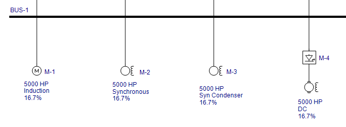
Motor type (induction, synchronous, synchronous condenser, or DC). This choice affects the motor impedances for short circuit calculations. The type also determines the one-line symbol for the motor. These are the symbols if that are produced for each of the motor types if the connection type is D (delta) or Y (wye), which are both ungrounded types:
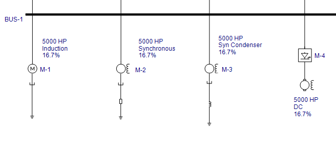
These are the symbols that are produced for each of the motor types if the connection is YG (grounded wye):
|

Motor kVA Calculations
There are two ways to calculate motor kVA in the Motor Specifications section of the motor dialog box. The one EasyPower uses depends on which fields you decide to enter. Below the kVA calculation methods are shown in priority order:
If the FLA is greater than 0, the motor kVA is determined by the following equation.
KVA = (1.73)(FLA)(kVmtr)
If the FLA is left blank or 0, the motor kVA will be determined from the following equation.
KVA = (HP)(0.746)/((EFF)(PF))
The above applies to the Motor Specifications kVA. The Short Circuit focus always uses the Motor Specifications kVA for a base value when calculating a motor’s short circuit current. However, the Power Flow focus, which uses the Motor Specifications kVA by default, has the option of using the real-time SCADA kW and kVAR values to calculate kVA. This option is in the motor Power Flow tab of the Motor Data dialog box.
DC Motor Specifications Tab
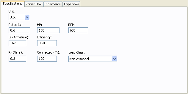
Figure 3: Specifications Tab for DC Motors
| Option | Description |
|---|---|
| Unit | Choose either US or Metric. |
| Rated kV | Motor rated kV. |
| Hp/kW | Motor rated horsepower (U.S. units) or kilowatts (metric units). |
| RPM | Revolutions per minute. |
| Ia (Armature) | Rated armature current in amps. |
| Efficiency | Ratio of output mechanical power to input power. |
|
R (Ohms) |
Armature resistance in ohms. This affects the short circuit contribution. |
| Connected (%) | Scales the short circuit contribution from the motor. |
| Load Class | To specify the class in terms of importance. You can select Essential, Critical, or Non-essential. This field does not affect analysis. It can be used in database query to distinguish a certain load class from others. See Advanced Query for more information. |
Short Circuit Tab
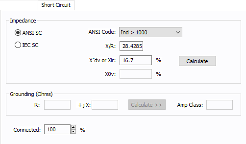
Figure 4: Short Circuit Tab of Motor Data Dialog Box
| Option | Description |
|---|---|
| ANSI SC |
Provides an easy way to enter ANSI Standard impedances and interrupting duty multipliers. Code numbers are chosen according to the motor types, sizes and modeling method. Regardless of the code chosen, ANSI Standard interrupting value multipliers are used. The codes available in this list change depending on what you have selected in the Type field of the Specifications tab. Using the ANSI Code field is the recommended method to enter motor impedances to assure that the proper interrupting duty impedance multiplier is used for ANSI Standard calculations1,2,3,4. See ANSI Code Impedances for more information. If the Adjustable Frequency Drive check box is selected in the Specifications tab, the following choices are available for the ANSI Code field:
Grouped motors with an adjustable frequency drive are non-regenerative motors and do not have contribution regardless of the motor type. Reference:
|
| IEC SC |
When this option is selected, IEC short circuit calculations are used. See IEC Impedance and X/R Calculations. If the motor has an adjustable frequency drive, you can also select the option for a regenerative or non-regenerative drive. Grouped motors with an adjustable frequency drive are non-regenerative motors and do not have contribution regardless of the motor type. |
| X/R | You can either type in the reactance to resistance ratio, or click Calculate to have EasyPower fill in this field. |
| X"d or Xlr |
Subtransient reactance in percent on the motor Hp base. Normally this is 16.7% for induction motors. If you have the locked rotor multiple (LRM) which is the ratio of the lock rotor current to the rated motor current, then you can calculate the impedance in percent using 100 / (LRM). |
|
X0v |
Saturated zero sequence reactance in percent on the motor’s MVA base. Zero sequence values are used in ground fault calculations. |
| Calculate | Click to have EasyPower fill the X/R and X" or Xlr fields. You can specify the average HP for grouped motors in Tools > Options > Equipment. |
|
Grounding Grounding impedances only apply to wye grounded connections. The units are R+jX in ohms. If you only know the ground amperes of the circuit, enter the amp class and use the Calculate button to calculate the grounding impedance. |
|
|
R |
Neutral ground resistance in ohms. Grounding resistors are usually given in amperes. The impedance is found from the following equation: R = Vln / I Only wye grounded motors (YG) are modeled with grounds. |
|
jX |
Neutral ground reactance in ohms. |
|
Calculate |
Click to have EasyPower fill in the R and jX fields (if the Amp Class is specified) or to fill in the Amp Class field (if R and jX are specified). |
|
Amp Class |
This is the current in amps through the ground impedance at the rated voltage. You can enter data in this field directly in amps or calculate it based on the voltage and ground impedance R +jX using Calculate. |
| Connected |
Provides an easy way to adjust the total motor horsepower used in determining short circuit currents. By changing the percent connected, the actual Hp (total connected value) entered in the Hp field can remain static. This reduces modeling errors and eliminates multiple databases for different contingencies. For example, an MCC has a group of induction motors (all over 50 HP) that add up to a total load of 600 HP. However, 300 HP is considered backup and is not on-line. In order to keep proper records of the MCC HP, 600 would be entered in the HP field. Since only 300 HP is spinning at any one time and can contribute short circuit current, the connected field is set to 50%. |
|
RMf / X"d |
The ratio of fictitious resistance to the subtransient reactance that is used in peak current calculations. If left blank, EasyPower calculates the value based on the IEC-60909 standard. This option appears for synchronous motors if the Show fields and X/R calculations based on IEC-60909 option is selected in Tools > Options > Equipment. |
ANSI Code Impedances
|
|
|
Momentary Duty |
Interrupting Duty |
|---|---|---|---|
|
Synch |
Synchronous |
1.0 X"dv |
1.5 X"dv |
|
Ind>1000 |
Induction Motor > 1000 Hp |
1.0 X"dv |
1.5 X"dv |
|
> 250 @ 3600 |
Induction Motor > 250 Hp at 3600 RPM |
1.0 X"dv |
1.5 X"dv |
|
>50 |
Induction Motor or Motor Group > 50 Hp |
1.2 X"dv |
3.0 X"dv |
|
<50 |
Induction Motor Group < 50 Hp |
1.67 X"dv |
Infinite X"dv |
|
Lumped |
Lumped Induction Motor Group |
1.0 X"dv (X=25%) |
3.0 X"dv |
Note: X" for induction motor groups >50 HP and <50 HP are typically assumed equal to 16.7%. Using the impedance multipliers, this corresponds to an equivalent motor contribution of 3.6 to 4.8 times the full load current.
IEC Impedance and X/R Calculations
|
Model |
Motor Type |
Impedance and X/R Calculations |
|---|---|---|
|
Individual |
Induction without AFD |
1) Calculate the MW per pole-pair by dividing MW by pole-pairs.
2) Calculate the X/R ratio of the motor.
Impedance is 16.7%. |
|
Group |
Induction without AFD |
Impedance and X/R are calculated as follows:
|
|
Individual or Group |
Induction with AFD DC with AFD |
Impedance is 16.7% and the X/R ratio is 10. |
|
Individual or Group |
Synchronous Synchronous Condenser |
Uses the ANSI default calculations for impedance and the X/R ratio. |
TCC Tab
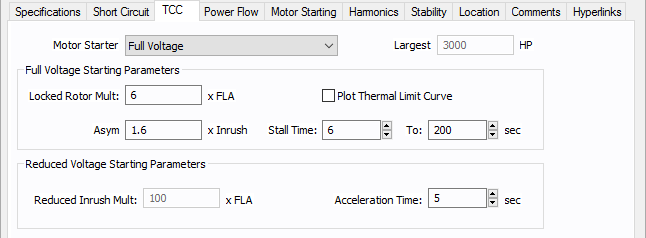
Figure 5: TCC tab of Motor Data Dialog Box
Power Flow Tab
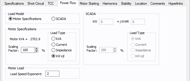
Figure 6: Power Flow Tab of Motor Data Dialog Box
DC Motor Power Flow Tab
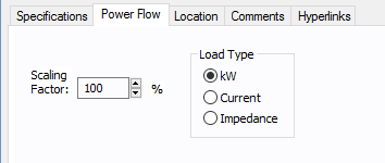
Figure 7: DC Motor Data - Power Flow
Motor Starting Tab
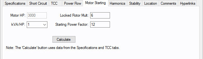
| Option | Description |
|---|---|
| Motor kW | The required input or rated power of the motor. |
| kVA/kW or kVA/HP | Represents the efficiency of the motor. It is a conversion factor for delivered power and the required input power. |
| Locked Rotor Mult | Equal to the inverse of the subtransient reactance (also known as X"dv) and provides the value at which the full load amp rating of the motor is multiplied under short circuit conditions. |
| Starting Power Factor | The momentary power factor during the start of the motor. While the motor is under starting conditions, the reactive power is higher than the real power as a result of the starting power factor. |
| Calculate |
Calculate uses data from the Specifications and TCC tabs to determine motor starting values. EasyPower references IEEE standards for the calculations. For example, if Motor Starter on the TCC tab is set to something other than Full Voltage, it affects the calculations. |
Harmonics Tab
Use the Harmonics tab to indicate whether this equipment item is introducing harmonics into your power system.
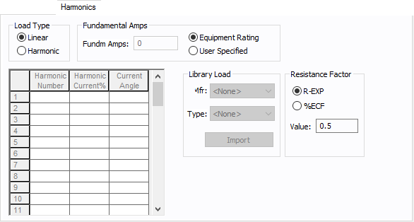
Figure 8: Harmonics Tab
| Option | Description | |||||||||||||||||||||
|---|---|---|---|---|---|---|---|---|---|---|---|---|---|---|---|---|---|---|---|---|---|---|
| Load Type |
The default is Linear, indicating the equipment does not produce harmonics. Choosing Harmonic makes the item an harmonic source and makes other fields in this tab available to edit. Note: For an adjustable frequency drive (AFD), the Load Type is always Harmonic. |
|||||||||||||||||||||
| Fundamental Amps |
Use to set the fundamental amps. The options are as follows:
To use fundamental current calculated by power flow, select Calculated from Power Flow in the Summation Fundamental Voltage area of the Harmonics Options > Control dialog box. |
|||||||||||||||||||||
| Harmonic Spreadsheet |
Use the spreadsheet to enter the harmonic spectrum produced by this item. You can enter up to 30 different harmonics in each equipment item. In the spreadsheet, enter the Harmonic Number (such as 5 for the 5th harmonic), the Harmonic Current in percent of the Fundamental Amps, and the Current Angle. By indicating the current angle, you can simulate transformer phase shift effects on rectifiers so appropriate canceling can take place. The harmonic may be integer or non-integer. |
|||||||||||||||||||||
| Library Load |
Common harmonic spectra may be entered from the device library. For instructions on how to enter your own spectra information, see Harmonics with Spectrum™. After selecting a particular device library spectrum from the Mfr and Type lists, click Import, and that spectrum is entered into the harmonic spreadsheet. |
|||||||||||||||||||||
| Resistance Factor |
EasyPower offers two methods for calculating RH:
RH = RFund * H R-EXP RH = RFund * (1+ECF*H2)/(1+ECF) EasyPower defaults all skin effect correction to R-EXP and a value of 0.5.
|
Stability Tab
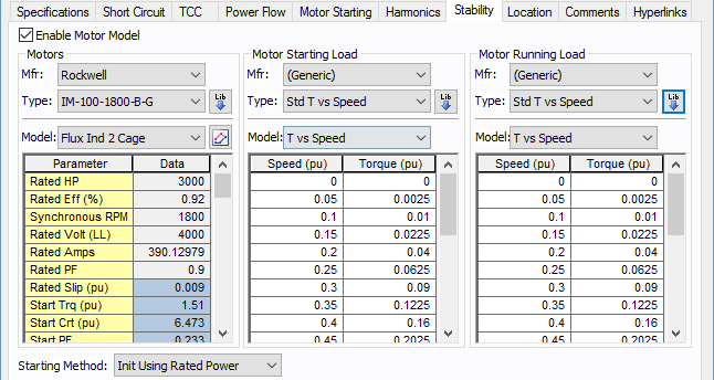
Figure 9: Stability tab of Motor Data Dialog Box
| Option | Description |
|---|---|
| Enable Motor Model |
Select the check box to enter stability information. Without this, you cannot run a dynamic simulation for the motor. |
| Motors | |
| Mfr | Provides a list of manufacturers available in the device library. If the desired manufacturer is not listed in the device library, you can add it to the library. |
| Type | Equipment types available from the selected manufacturer. If the desired type is not listed, you can add it to the library. |
 Lib Lib |
Populates the table with equipment data from the library. See EasyPower Device Library for more information. |
| Model | Equipment models available from the selected equipment type. If the desired model is not listed, you can add it to the library. |
 Define Parameters Define Parameters |
Enables you to obtain an estimate of the motor circuit parameters from the torque vs. speed characteristics. See Define Motor Parameters (Step 1) . |
| Starting |
This setting selects the method by which the motor will be initialized. The two options for this setting are:
Explanation: There are conditions where a motor parameter derivation has significant errors in rated conditions (such as upwards to 10%) when attempting to match a manufacturer's torque vs. speed curve. This is most likely created by inconsistencies in the supplied data for various reasons. For such conditions, initializing to rated power defined by the power flow causes a new slip to manifest through initialization, which is not equal to the specified rated slip. This then creates a condition where the torque produced by the motor during starting can be significantly greater than the torque vs. speed curve generated in the parameter derivation. For a motor in a borderline start condition (near stalling), the results may show an incorrect successful start (we have seen up to 12% greater torque over the motor's speed range). To correct for this, select "Init Using Rated Slip". This will force the motor to re-create the exact torque vs. speed curve generated in the parameter derivation. Note however that the rated conditions reached after starting will have the error accepted in the parameter derivation. |
|
Motor Starting Load This section defines the model for load characteristics while the motor is starting. |
|
| Mfr | Provides a list of starting load characteristics available in the device library. |
| Type | Starting load types available from the manufacturer selected in the Mfr field above. |
| Model |
Lists available starting load models in the library. The choices are:
|
|
Lib |
Populates the table with equipment data from the library. See EasyPower Device Library for more information. |
|
Motor Running Load This section defines the model for load characteristics while the motor is running. |
|
| Mfr | Provides a list of manufacturers available in the device library. If the desired manufacturer is not listed in the device library, you can add it to the library. |
| Type | Equipment types available from the selected manufacturer. If the desired type is not listed, you can add it to the library. |
| Model | Equipment models available from the selected equipment type. If the desired model is not listed, you can add it to the library. |
|
Lib |
Populates the table with equipment data from the library. See EasyPower Device Library for more information. You can also use the Define Motor Parameters feature described below to derive the motor parameters. |
Define Motor Parameters (Step 1)
Click Define Motor Parameters to obtain an estimate of the motor circuit parameters using the name-plate values and the speed-torque curve of the motor. Notes provided in the upper left corner of this window are instructions on how to use this tool to derive the motor parameters.
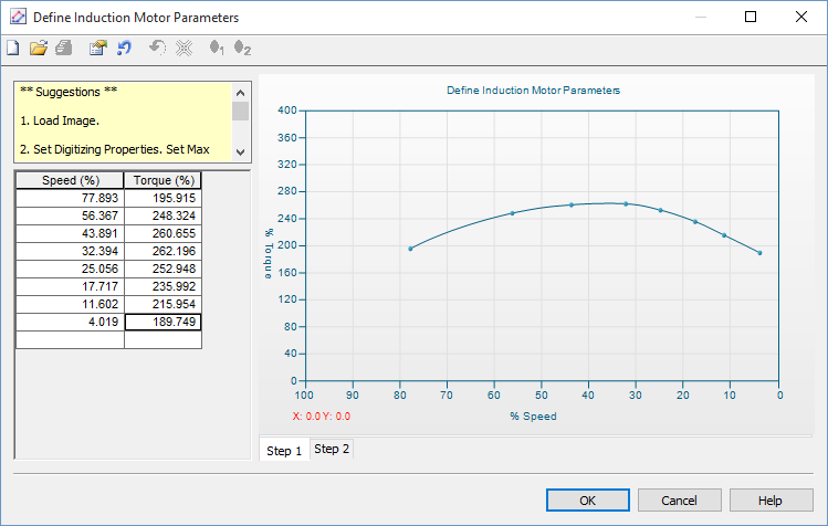
Figure 10: Define Induction Motor Parameters-Step 1
| Option | Description |
|---|---|
 Load image Load image |
Enables you to load an image of the motor curve to be digitized. |
 Set max torque Set max torque |
Enter motor maximum torque in %. |
 Flip speed axis Flip speed axis |
Curve axis can be flipped to match the manufacturer. |
Define Induction Motor Parameters (Step 2)
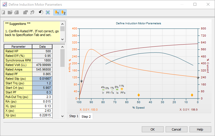
Figure 11: Define Induction Motor Parameters-Step 2
| Option | Description |
|---|---|
|
Gravity Points |
The gravity points are movable points used to optimize the derived torque speed curve to the actual torque speed curve. |
|
Flip speed axis |
Curve axis can be flipped to match manufacturer. |
|
Minimize |
The Minimize button attempts to reduce the error. |


Other Tabs
See Common Tabs for information on the Location, Reliability, Comments, Hyperlinks, Media Gallery, or Collected Data tabs.
More Information
| Database Technical Reference | Common Tabs |
| Media Gallery |