Tool Point of Connection Data
Use the tool point of connection to connect a tool to the one-line. A tool is a piece of equipment that can potentially have multiple different points of connection to the electrical system.
The point of connection represents the combination of both a bus and a load. This combination enables you to perform arc flash calculations on the bus and load as a unit.
This dialog box includes the following areas and tabs:
- Database Dialog Box Toolbar
- Connection Information
- Specifications Tab
- Description Tab
- Harmonics Tab
- Arc Flash Hazard Tab
See Common Tabs for information on the Location, Reliability, Comments, Hyperlinks, Media Gallery, or Collected Data tabs.
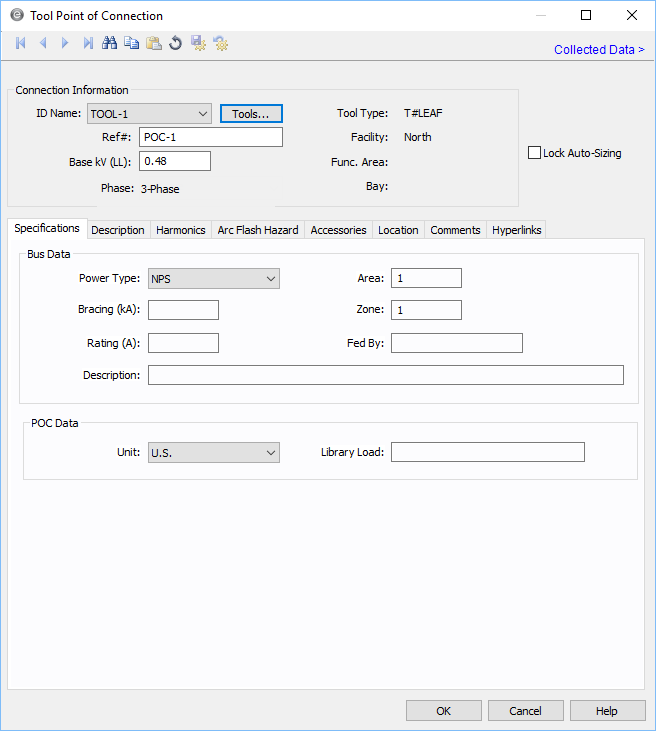
Figure 1: Tool Point of Connection Data Dialog Box
Connection Information
| Option | Description |
|---|---|
| Tool ID | The identifier for the tool. You can select from the list, or click Tools to create a new tool. See Edit Tools for more information. |
| Ref# |
The reference number for the point of connection. This information appears on the one-line. |
| Base kV |
Base kV for the tool point of connection. Note that the tool point of connection must have a kV entered before equipment can be connected to it. Anything less than 1 kV is considered low voltage, anything 1 kV or more is high voltage. |
|
Phase |
The phase of the item. Currently, this is for reference only.
|
| Tool Type | This represents a type of tool. |
| Facility | The facility where the tool point of connection exists. This information comes from the tool. See Edit Tools for more information. Facilities are set up under Tools > Options > Facilities. |
| Func. Area | The functional area where the tool point of connection exists. This information comes from the tool. See Edit Tools for more information. |
| Bay | The bay where the tool point of connection exists. This information comes from the tool. See Edit Tools for more information. |
| Lock Auto-Sizing | When this check box is selected, the tool point of connection cannot be auto-sized. |
Specifications Tab
Description Tab
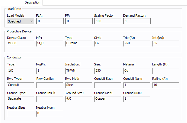
Figure 2: Description Tab
Load Data
| Option | Description |
|---|---|
| Load Model | Select from Specified (user-entered) data or from SCADA (Supervisory Control and Data Acquisition) data. SCADA data can be imported by clicking File > Import. |
| FLA | Full load amps (rated continuous current) of the load. The point of connection load is treated as a constant kVA load model when performing power flow calculations. |
| PF | Power factor for the load. |
| Scaling Factor | Each load can be varied by applying a different scaling factor. This lets you model the actual panel or lumped load on a bus, then study different loading conditions. This allows quick “what if” studies and prevents errors that occur from data entry. |
| Demand Factor | Demand factor for the load. |
| Protective Device |
The protective device information comes from the breaker located between the point of connection and the bus. |
| Conductor |
The conductor information comes from the cable that joins the point of connection with the bus. |
Harmonics Tab
Use the Harmonics tab to indicate whether this equipment item is introducing harmonics into your power system.
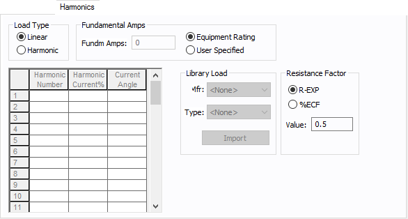
Figure 3: Harmonics Tab
| Option | Description | |||||||||||||||||||||
|---|---|---|---|---|---|---|---|---|---|---|---|---|---|---|---|---|---|---|---|---|---|---|
| Load Type |
The default is Linear, indicating the equipment does not produce harmonics. Choosing Harmonic makes the item an harmonic source and makes other fields in this tab available to edit. Note: For an adjustable frequency drive (AFD), the Load Type is always Harmonic. |
|||||||||||||||||||||
| Fundamental Amps |
Use to set the fundamental amps. The options are as follows:
To use fundamental current calculated by power flow, select Calculated from Power Flow in the Summation Fundamental Voltage area of the Harmonics Options > Control dialog box. |
|||||||||||||||||||||
| Harmonic Spreadsheet |
Use the spreadsheet to enter the harmonic spectrum produced by this item. You can enter up to 30 different harmonics in each equipment item. In the spreadsheet, enter the Harmonic Number (such as 5 for the 5th harmonic), the Harmonic Current in percent of the Fundamental Amps, and the Current Angle. By indicating the current angle, you can simulate transformer phase shift effects on rectifiers so appropriate canceling can take place. The harmonic may be integer or non-integer. |
|||||||||||||||||||||
| Library Load |
Common harmonic spectra may be entered from the device library. For instructions on how to enter your own spectra information, see Harmonics with Spectrum™. After selecting a particular device library spectrum from the Mfr and Type lists, click Import, and that spectrum is entered into the harmonic spreadsheet. |
|||||||||||||||||||||
| Resistance Factor |
EasyPower offers two methods for calculating RH:
RH = RFund * H R-EXP RH = RFund * (1+ECF*H2)/(1+ECF) EasyPower defaults all skin effect correction to R-EXP and a value of 0.5.
|
Arc Flash Hazard Tab
EasyPower calculates arc flash risk assessment results using the options set on the Arc Flash Hazard tab. The results are calculated for automatic transfer switches, buses, tool points of connection, MCCs, and panels.
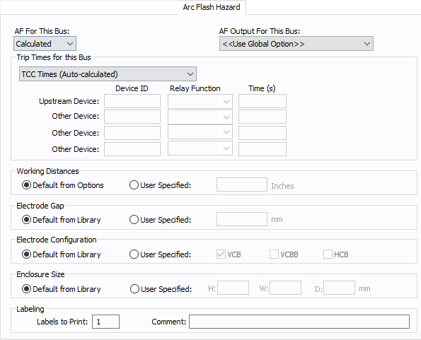
Figure 4: Arc Flash Hazard Tab
| Option | Description |
|---|---|
| AF For This Bus |
You can specify how you would like arc flash results determined for this bus using AF for this Bus. Calculated: When the bus is faulted, EasyPower the performs arc flash hazard analysis using the calculation method specified in Short Circuit Options. EasyPower uses other settings on this tab as part of the calculations. Excluded: Select to exclude the bus from arc flash reports. An example of when you might select this option is for a bus that is required to model the electrical parameters of the system but does not actually represent a piece of electrical equipment. Other applications include nodes and tap-offs (junctions), where energized work is not required. Forced To: When you select this option, you can enter the incident energy and arc flash boundary for this bus. The incident energy and arc flash boundary values are shown on the one-line and in reports and work permits. This can be used for instances where you need to apply a calculation that is outside the scope of the industry standard calculations. |
| AF Output For This Bus |
You can specify whether to display results on the line side or the load side of the Main protective device of the bus equipment. If the arc flash hazards output for this bus needs to be different from the global option, use this field. The choices are:
|
| Trip Times for this Bus |
You can select the method for determining trip times for this bus by choosing from the following:
Note: When a user-defined time is specified and the calculation method is set to use the integrated method, only the upstream device setting is used. The time is considered as the maximum length of the simulation. See The Integrated Method for more information. |
| Working Distances |
You can specify the working distances shown on the one-line and in reports and work permits.
The units displayed are based on the units selected in Arc Flash Hazard Options on the System tab. For inches, the range is 1-1000. For meters, the range is 0.1 to 1000. |
| Electrode Gap |
You can specify the electrode gap shown on the one-line and in reports and work permits.
|
|
Electrode Configuration |
You can specify the electrode configuration shown on the one-line and in reports and work permits.
Electrodes in Enclosures: Electrodes in Open Air: You can select more than one configuration to represent the multiple types of conditions that can occur for the equipment. EasyPower evaluates each configuration and then provides values for the highest incident energy based on the existing electrode configurations. Annex C in the IEEE 1584-2018 standard describes examples where you might use more than one electrode configuration. Tip: To change the electrode configuration for multiple items on the one-line, select the items in the Database Edit focus and then on the Home tab, click Change > AF Bus Electrode Configuration. Electrode configurations are only applicable to the IEEE 1584-2018 standard. For more information, see Electrode Configuration. |
|
Enclosure Size |
You can specify the enclosure size shown on the one-line and in reports and work permits.
The units displayed are based on the units selected in Arc Flash Hazard Options on the System tab. For inches, the range is .01-1000. For millimeters, the range is 0.1 to 25,000. The enclosure dimensions affect arc flash.
|
| Labels to Print |
Enter the number of labels you want to print for arc flash hazard analysis. If you enter "0," no labels will print. |
| Comment |
You can type a comment that appears on the arc flash label when it is printed. For example, you could type a location description for the equipment to assist with label placement. |
Other Tabs
See Common Tabs for information on the Location, Reliability, Comments, Hyperlinks, Media Gallery, or Collected Data tabs.
More Information
| Database Technical Reference | Common Tabs |
| Edit Tools | Electrode Configuration |
| Media Gallery |