Design Library
The design library is a template for sizing various types of equipment. Equipment sizing is based on the type of circuit and the amp calculation for the circuit. The library comes with a design template named “Generic,” which consists of a list of protective devices, cables, bus equipment and transformers to select from. You can use the Generic design template for typical applications. You can also create your own design template, or modify the Generic template to suit your specific needs.
To open the library, while in Database Edit focus, click File > Open Library. Select the file Stdlib.mdb or your custom library.
The Generic design template can be found in the section Design > US > Generic.
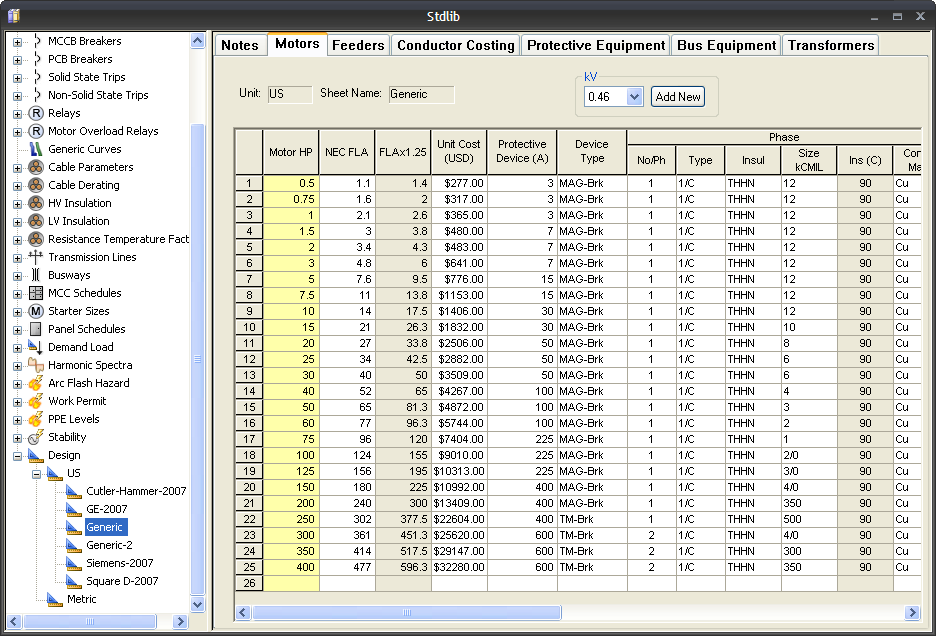
Figure 1: Auto Design Library
A design template is also called Design Sheet. Each design sheet is organized into various tabs, which have spreadsheets describing equipment and sizes to select from. The following tabs are available. The details are provided later in the documentation.
|
Tab |
Description |
|---|---|
| Notes | To describe the design aspects, and provide notes and comments. |
| Motors | For sizing protective devices and cables in motor circuits based on motor size. See Motors. |
| Feeders | For sizing cables. See Feeders. |
| Conductor Costing | Contains a list of conductors and their costs. See Conductor Costing. |
| Protective Equipment | Contains lists of protective devices (circuit breakers, fuses) for various type of bus equipment such as switchgear, panelboards, MCC, and so on. See Protective Equipment. |
| Bus Equipment | Contains lists of bus sizes for various type of bus equipment such as switchgear, panelboards, MCC, and so on. See Bus Equipment. |
| Transformers | Contains a list of transformers of various sizes and kV. See Transformers. |
Motors
The design template for motor circuits is entered in this part of the library. A motor circuit consists of a motor, cable, and a protective device.
| Option | Description |
|---|---|
|
kV |
Rated kV for the motors. The motor rated voltage must be defined in the library. Use Add New to create new voltage levels. Each kV level has its own design template. The motor voltage in the one-line must be exactly equal to the voltage defined in the library for Auto-Design to work. A mismatch of voltage yields no results. You can add any number of voltage levels for motors. To view or edit data for any voltage level, select the kV first. To delete a kV value, delete all the cells in the spreadsheet for that kV. |
|
Motor HP |
Rated horsepower (HP) for the motor for which circuit is to be designed. The HP for the motor in the one-line must match the design library Motor HP. You must enter the Motor HP before you can enter other details for that circuit. Deleting the Motor HP deletes the details. Note: The cables and protective devices in the motor circuits are designed as per the motor HP. |
|
NEC FLA |
Full-load current for the motor based on National Electric Code (NEC 2005), Table 430.250. The FLA is determined from motor voltage and size (HP). |
| FLAx1.25 |
This is NEC FLA multiplied by a factor of 1.25. |
|
Protective Device (A) |
Continuous current rating for the device protecting the motor circuit. |
|
Device Type |
Type of protective device such as fuse or circuit breaker. This field is currently used for database purposes only and is not used in calculations. |
|
Phase |
Details of the phase conductors for motor circuits. |
|
No/Ph |
Number of conductors in each phase. |
|
Type |
Core construction such as 1/C, 3/C, and so on. |
|
Ins |
NEC/UL insulation designation. |
|
Size kCMIL |
Size of conductor in AWG or kcmil. |
|
Ins (C) |
Maximum operating temperature for the cable based on insulation type. This is defined in the cable data library, and is automatically filled in once you select the cable details. |
|
Cond Matl |
Conductor material—either copper (Cu) or aluminum (Al). |
|
Ground |
Details of ground conductors for motor circuits. |
|
No/Ph |
Number of ground conductors. |
|
Size kCMIL |
Size of conductor in AWG or kcmil. |
|
Raceway |
Details of conductor raceway. |
|
Type |
Type of enclosure for cables, such as conduit, tray, air, burial, and so on. |
|
Material |
Material type for the enclosure, such as steel aluminum, PVC, and so on. |
|
Conduit No. |
Number of conduits. |
|
Conduit Size (in) |
Diameter of conduits in inches. |
|
Ampacity |
Current carrying capacity of the cables for continuous loads. The program automatically obtains the ampacity values from the cable library. |
|
Terminal Ampacity @ 75 deg C |
Ampacity for cable terminations. The program automatically computes the terminal ampacity from the cable ampacities. |
Feeders
The design template for feeder circuits is entered in this spreadsheet. Feeder circuits are sized by the upstream protective device amps. For the meaning of individual column headings, see Motors. You can have feeder designs for 3 Phase – 3 Wire systems or 3 Phase – 4 Wire systems. Select the appropriate system before entering data into the spreadsheet.
The first column in this spreadsheet is Protective Device (A). The feeder is designed based on the protective device amp rating. Deleting this cell deletes the data in the entire row.
Conductor Costing
Conductor costs are listed here.
| Option | Description |
|---|---|
|
Class |
The class of the conductor (for example, Phase, Ground, Conduit). |
|
Type |
The type of conductor (for example, I/C, 3/C, IAS). |
|
Insul |
The insulation used for the conductor (for example, THHN). |
|
Size |
The size of the conductor. |
|
Unit |
The units associated with the size. |
|
Material |
The conductor material (for example, Cu, AL, Steel). |
|
Cost/ft |
The cost per foot for the conductor. |
Protective Equipment
Protective devices to be used with various equipment types, circuit types and continuous current rating are defined in this section.
| Option | Description |
|---|---|
|
Equipment |
The various equipment types are switchgears, switchboards, panelboards, and so on. For each equipment type, you can enter various protective device amps. |
|
Rating (A) |
Continuous current rating of protective device. |
|
Appl |
The type of circuit for which the protective device selection is applicable. The circuit type can be motor circuit, feeder/transformer circuit, or all types. |
|
Add Breaker |
This button opens the Add Breaker to Design Sheet dialog box for you to specify multiple possible solutions to breaker selection. The fields of the dialog box are described below. The first row in this sheet is shown in the Design Sheet view. While performing Series Coordination of breakers, the specified breakers inside this dialog are evaluated, and the first breaker to be selectively coordinated with the downstream breaker is selected.
|
Bus Equipment
This section is used for defining the bus ratings for various equipment types.
| Option | Description |
|---|---|
|
Equipment |
Type of equipment such as switchgear, panelboard, and so on. |
|
Bus Amperes |
Various ampere ratings to be used in design for each type of equipment. |
|
Description |
Enter a description of the equipment—for example, manufacturer and type. |
|
Bus Bracing kA |
Equipment Bus rating in kA. |
|
Bus Material |
Material type for equipment—Cooper or Aluminum. |
|
Unit Cost |
Equipment unit cost used for Bill of Material. |
Transformers
The transformers to be used in design are defined in this section. You can enter transformer sizes for various voltage levels.
| Option | Description |
|---|---|
|
kV |
The primary and secondary kV of transformers are displayed in the list. To add any new kV level not in the list, click Add New and enter the primary and secondary voltages for the transformers. To delete any voltage level, delete all the spreadsheet entries for the level. |
|
Base kVA |
Transformer self cooled rating in kVA. |
|
Z% |
Percent impedance of transformer. |
|
Type |
Insulation/cooling medium, such as oil, gas, dry, and so on. |
|
Class |
Cooling class designation. |
|
Temp |
ANSI temperature rating of the transformer. Various combinations can be selected and are dependent upon the type of transformer. Dual ratings such as 55/65 increase the overload capability of the transformer by 12 percent. |
|
Cooled Rating (kVA) |
Forced cooled rating /overload rating in kVA. |
|
Pri FLA |
Primary full load amps. |
|
Pri Brkr/Fuse Amps |
Amp value used for selecting primary side protective device. |
|
Sec FLA |
Secondary full load amps. |
|
Sec Brkr/Fuse Amps |
Amp value used for selecting secondary side protective device. |
More Information
| Auto Design | Performing Auto Design |
| Editing the Design Library | Reports |
| Auto Design Options | Adding Coordination Data to the Breaker Library |