Bus Tie Breakers and Switches
A bus tie breaker or switch goes between two buses rather than between a bus and a piece of equipment.
Click the  LV Breaker palette button.
Place the breaker by positioning the breaker pointer's top leader line on the right end of the bottom middle bus and clicking (see figure below). The breaker automatically attaches to the bus. If you miss (the breaker doesn't connect and stays all red), use the  Select pointer and drag the symbol into position.
Move the pointer over the breaker and right-click. Edit options appear as shown in the figure above. Click Rotate > 90°. The breaker orientation changes from vertical to horizontal. At the same time, the connection type of the breaker changes from feeder breaker to bus tie breaker. Drag the tie breaker's remaining leader to the bottom right bus. After it connects, drag the tie breaker's symbol to be centered between the two buses. After the tie breaker is connected to buses on both sides, the Rotate command only changes the orientation in the one-line diagram, and the bus remains as a tie breaker.
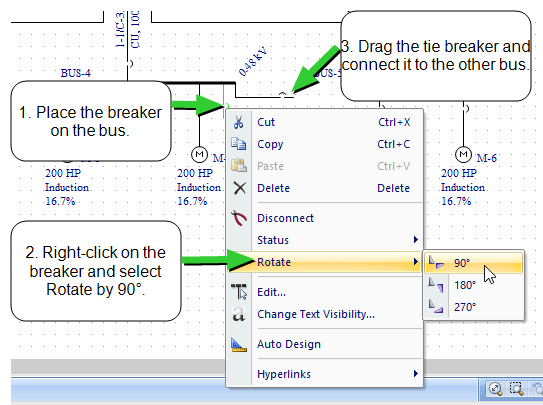
Figure 1: Adding a Tie Breaker
Note: To create a tie breaker between two buses, the buses must be of the same phase and connection type.
Only one tie breaker per bus is allowed. However, you can model ring buses or breaker and a half schemes by using a breaker inserted into a short section of busway instead of a tie breaker.