Colors Tab
EasyPower's customizable options are set up under Tools > Options.
The Colors tab lets you change the appearance of the screen and printer elements. You can select a color palette based on the phase type or on the voltage range.
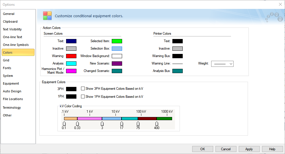
Figure 1: Colors Tab of the Options Dialog Box
Most colors can be changed independently for the screen and printer. This accounts for issues where color printers do not always render screen colors well.
To change color of any item, click the box showing the current color format. In the color palette that appears, select the desired color. The change takes place immediately. Click More if you want to create or use custom colors.
Click Apply to save your color changes without closing the dialog box, or click OK when you have the colors you want.
The program uses the equipment colors selected for the phases as the default equipment colors. You can also have the program display the color of each equipment item based on where it falls within the kV range. You can do this for 3-phase equipment, 1-phase equipment, or both 3-phase and 1-phase equipment (by selecting both check boxes).
Note: If individual equipment items have been formatted to use a certain color (using the Color button on the Home tab), then that color is used instead of the default colors specified here.
Option Descriptions
|
Option
|
Description
|
|
Screen Colors
|
|
Text
|
This sets the color of the text on the one-line, such as the item ID text or analysis results.
|
|
Inactive
|
This sets the color of an item that has been turned off using the Deactivate option.
|
|
Warning
|
This color indicates that something is lacking or wrong with a particular item. The exact meaning is context-specific. For example, in the Database Edit focus it means either the item is not fully connected or the item's data is incomplete. In the Short Circuit focus, it could mean that a breaker is being overloaded.
|
|
Analysis
|
This color is most commonly used for buses that have been faulted in a short circuit analysis or buses at which harmonics are injected during harmonics analysis.
|
|
Harmonics Plot / Maint Mode
|
This sets the color of harmonics plots used in Define Plot, or to indicate equipment where maintenance mode is turned on.
|
|
Selected Item
|
This sets the color for when you click on an item to select it on the one-line, or drag a rectangle around a group of items to select them, or use the Find-Select feature to find one or more items.
|
|
Selection Box
|
This sets the color of the selection box on your screen.
|
|
Window Background
|
This sets the color of the background of the screen in the one-line.
|
|
New Scenario
|
While in a scenario, any new items are indicated with this color.
|
|
Changed Scenario
|
While in a scenario, any equipment data or location changes are indicated by this color.
|
|
Printer Colors
|
|
Text
|
This sets the color of the text on the one-line, such as the item ID text or analysis results.
|
|
Inactive Color
|
This sets the color of an item that has been turned off using the Deactivate option.
|
|
Warning Color
|
This color indicates that something is lacking or wrong with a particular item. The exact meaning is context-specific. For example, in the Database Edit focus it means either the item is not fully connected or the item's data is incomplete. In the Short Circuit focus, it could mean that a breaker is being overloaded.
|
| Warning Bus |
Buses that are highlighted (such as to show which buses are faulted or have a violation) can be given a different color that makes them distinguishable from non-highlighted buses.
|
| Warning Line |
Non-bus items that are highlighted (such as to show line end faults or equipment duty violations) can be printed bolder to make them distinguishable from non-highlighted items. This is especially useful on monochrome printers like the HP LaserJet.
|
|
Analysis Bus
|
This color is most commonly used for buses that have been faulted in a short circuit analysis or buses at which harmonics are injected during harmonics analysis.
|
|
Equipment Colors
|
|
Show Equipment Colors Based on kV
|
This sets the equipment colors based on the phase of the item. You can specify whether to set the color for 3-phase equipment, 1-phase equipment, or both. Click the color to open the color palette to change it.
Note: To avoid confusion, make sure that the equipment color is not the same as the warning or analysis color.
|
|
kV Color Coding
|
This sets the equipment colors based on a voltage range. There are color codes for different voltage ranges and sliders that represent the boundary voltage of each color code. You can set the color for the different voltage ranges between 1 kV and 1000 kV.
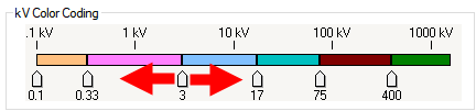
Drag each slider to the left and right to set the boundary voltage for each range. The kV value appears below each slider as you adjust the position.
To change the color for any range of voltage, click the color in the range and then select the desired color from the color palette.
|
More Information