About Panel Rows
The phases and number of poles for the circuit affect the panel row behavior. Below is an image of a three-phase panel with a mixture of poles. When the Fixed Phase Arrangement check box is selected, the phases appear diagonally for each row, with phase A in the first row in the first column, phase B in the second row in the second column, and phase C in the third row in the third column. This phase pattern repeats throughout the spreadsheet.
The number of poles indicates how the rows are grouped together to make up a circuit. For example, rows 13-17 are grouped because the number of poles is set to 3. Rows 19-21 are grouped together because the number of poles is set to 2. The remaining rows are all individual because the poles are set to 1.
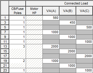
Figure 1: Panel Rows in 3 Phase (Detailed View) Using Fixed Phase Arrangement
For single phase, the pattern is similar, but for a 3-wire service, it only spans across two columns, and the number of poles selected can only be 1 or 2.
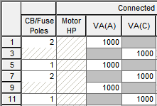
Figure 2: Panel Rows in Single Phase (Detailed View for a Single-Phase, 3-Wire Service)
For a single phase, 2-wire service, there is only one column, and the number of poles selected can only be 1.
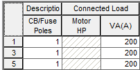
Figure 3: Panel Rows in Single Phase (Detailed View for a Single-Phase, 2-Wire Service)