Tutorial - Creating a One-line
This tutorial describes the basic steps to create a one-line. For more detailed instructions, refer to "Making One-Line Diagrams" in Help.
After starting EasyPower, click File > New > New Oneline to open a blank one-line diagram in the session window.
Tip: If you are viewing the Start Page, you can click New to open a blank one-line.
The EasyPower session window displays the EasyPower program options. The inner area of the window displays additional windows such as the Start Page, one-lines, or the device library. You can have one or multiple windows open in the inner area. Click the  Maximize button on the upper-right corner of the session window to make the window fill your screen.
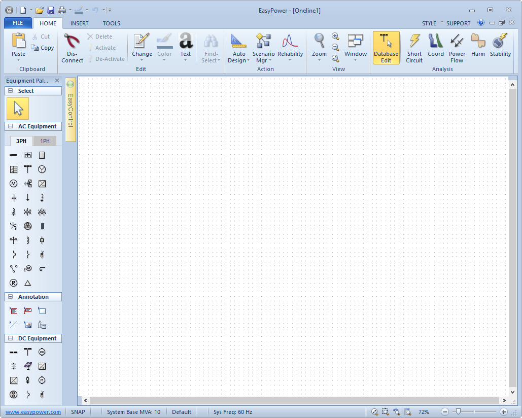
Figure 1: The EasyPower Session Window
Adding Buses to the One-line
The central equipment type of every one-line is the bus. A bus defines the connection point for two or more pieces of equipment. Equipment items which are not yet connected to a bus are highlighted in red.
To add a bus to the one-line, click  Bus in the Equipment Palette or Insert tab. The pointer changes to the shape of a bus as you move back to the one-line. Click on the location where you want to position the bus. You can continue adding buses in this way until you click on another palette button.
Place buses in the drawing as shown below by clicking the left mouse button and dragging each bus to the one-line.
Tip: You can set a default base kV for new buses by selecting Tools > Equipment > Bus.
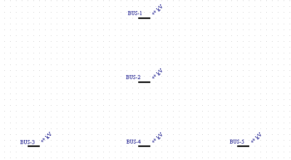
Figure 2: Inserting Buses
Adjusting Bus Sizes and Locations
With the pointer set as a selection arrow, you can move and size the buses. You move buses or ID names by dragging them with the left mouse button.
- When you bring the pointer close to a bus, a four-headed arrow
 appears. Left-click and drag to move the bus.
 - When you move the pointer close to the either end of the bus, a double-headed arrow ↔ appears. Change the size of a bus by dragging either end of it with the left mouse button. You can even shrink it to a single dot or “node” so that it takes up less room.
After experimenting with moving and sizing the buses, arrange them as shown below.
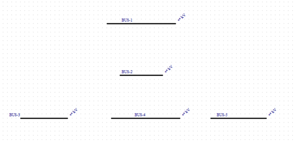
Figure 3: Moving and Sizing Buses
Entering Bus kV Data
When you add a bus to the one-line, you must provide the kV of that bus before you can attach anything to it. You can either set a default kV ahead of time (before adding the bus to the one-line) by clicking Tools > Equipment > Bus and specifying the base kV, or you can set it afterward by double-clicking on the bus to bring up its data dialog box.
Enter the bus data by double-clicking on each of the bus symbols with the select pointer  . The Bus Data dialog box is displayed each time and you can enter the base kV for the bus and then click OK to save the change. Use 13.8 kV for the top bus and 0.48 kV for the others. You can also
change the ID names to make them more descriptive.
. The Bus Data dialog box is displayed each time and you can enter the base kV for the bus and then click OK to save the change. Use 13.8 kV for the top bus and 0.48 kV for the others. You can also
change the ID names to make them more descriptive.
Copy and Paste
To save time when entering similar equipment items, you can copy and paste the equipment data. To do this:
- Use the pointer to select the equipment item with that has the information you want to copy. The item turns green to indicate that it is selected.
- Click
 Copy.
Copy. - Select a different item (or group of items). You can drag a selection box around a group of items to select multiple items. Don't worry if you include other types of equipment in your selection area--only the information for similar equipment gets copied.
- Click
 Paste. Note that the information from the first item is copied to the selected equipment items.
Adding a Transformer
- Click
 Two Winding Transformer on the Equipment Palette or Insert tab—the pointer changes to a two winding transformer symbol.
 - Place the transformer by positioning the transformer pointer's top leader on the top bus and clicking once. The transformer
automatically attaches to the bus, and the top half of the symbol turns black. If you miss (the transformer doesn't
connect and remains red), switch back to the select pointer if needed and drag the symbol into position.
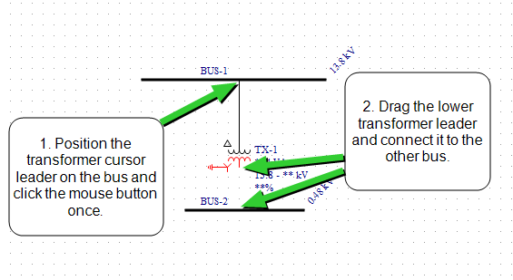
Figure 4: Adding a Transformer
- With the select pointer active, use the left mouse button to drag the transformer's
remaining leader to the middle bus (see figure above). The transformer stays red until it is connected. After it connects, you can drag the transformer symbol up so it is centered
between the two buses, if needed.
- Double-click on the transformer to enter the transformer data. Important entries are noted with a red exclamation mark. You can still save the data without those entries being made, but will not be able to perform analysis until the entries are complete. Use the Calculate buttons to have EasyPower calculate values for you. Click OK when finished.
Adding Cables
- Click
 Cable on the Equipment Palette—the pointer changes into a crosshair. Put the crosshair on
the middle bus and click the left mouse button (but don't release it yet). This sets one end of the line. Now drag the
crosshair to the left bottom bus (as shown in the figure below) and release the mouse button. This places the cable.
Cable on the Equipment Palette—the pointer changes into a crosshair. Put the crosshair on
the middle bus and click the left mouse button (but don't release it yet). This sets one end of the line. Now drag the
crosshair to the left bottom bus (as shown in the figure below) and release the mouse button. This places the cable.
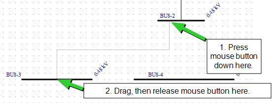
Figure 5: Adding Cables
- Repeat this for the other cables. Note that you can move the cables by dragging them with the select pointer.
- Double-click on the cables to enter cable data.
Adding Motors
- Click
 Motor on the Equipment Palette—the pointer changes into a motor symbol.
 - Place the first motor by positioning the motor pointer's leader on the bottom left bus and clicking. The motor automatically attaches to the bus, and the symbol turns black. If you miss (the motor doesn't connect and turns red), drag the symbol into position after pressing the button.
- Continue by attaching a second motor to the bus.
- Double-click on each of the motors to enter motor data.
Tip: You can copy data from one motor to another by using the copy and paste functions, as described in Copy and Paste.
Adding a Utility
- Click
 Utility on the Equipment Palette—the pointer changes into a utility symbol.
 - Place the utility by positioning the utility pointer's leader on the top bus and clicking.
- With the select pointer , double-click on the utility to enter utility data.
Adding Feeder Breakers
- Click
 LV Breaker on the Equipment Palette or Insert tab—the pointer changes into a low voltage breaker
symbol.
LV Breaker on the Equipment Palette or Insert tab—the pointer changes into a low voltage breaker
symbol. - Position the breaker pointer directly over a feeder line (such as a cable or transformer) and click the left mouse button (see
figure below). The breaker is inserted into the line.
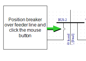
Figure 6: Adding Feeder Breakers
- If you miss (the breaker doesn't insert into the line and remains red), drag the breaker to the feeder line and release the mouse button so that the breaker is connected to the feeder.
- Place low voltage breakers on the feeder lines between the equipment items.
- With the select pointer, double-click on the breakers to enter breaker data.
Viewing the Entire One-line
On the Home tab, click  Zoom Out Full to center your entire one-line on your screen.
Conclusion
Congratulations! You just entered a power system one-line with EasyPower. You can apply what you have learned to your real-world systems. For an example of a larger completed one-line, open the Bigger.dez database in the Samples directory. You can experiment running analysis with this file by selecting the Short Circuit, Power Flow, or Harmonics focuses.
The EasyPower Help topics cover this and other features in greater
depth. To open Help, click  Help in the upper-right corner of the EasyPower window or press F1. You can find additional detailed instructions regarding creating one-lines in the "Making One-Line Diagrams" topic.