Tutorial - Protective Device Coordination (IEC)
This tutorial will guide you through several of the main features in EasyPower’s PowerProtector™ coordination program.
Coordination Focus
To perform protective device coordination, you must be in the Coordination focus.
- From the File menu, click Open File.
- Open the Protection-IEC.dez file in your Samples directory.
- Click
 Maximize on the one-line window, if needed, to fill the session window with the one-line.
 - Click
 Coordination to open the Coordination focus.
Tip: If you are viewing the Start Page, you can click Open One-line instead.
Opening a TCC
- Click
 Open TCC.
 - In the Open TCC dialog box, select TCC-1 and click Open to open the TCC.
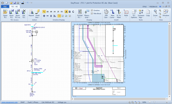
Figure 1: TCC Plot
Dynamic Coordination of Curves
The EasyPower TCC window supports dynamic dragging of all protective device curves. This provides an easy and smooth interface for changing the equipment settings.
Hover over the relay R-6 in the TCC plot until a double-headed arrow appears, and then drag the curve up and down. The relay time dial changes dynamically. The tooltip indicates the latest time dial setting.
Note: Relay settings can also be modified through the relay dialog box by double-clicking on the relay.
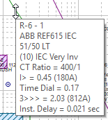
Figure 2: Dynamic Coordination of TCC Curves
TCC One-lines
There are two one-lines in the TCC window: one located inside the TCC, and one located to the left of the TCC. (We refer to them as the “inside one-line” and “left one-line” in this tutorial.)
The inside one-line always displays a zoomed-out view of the left one-line. This provides WYSIWYG screen viewing of the printed TCC. This inside one-line box can be moved and resized as shown in figure below.
In the left one-line, equipment items can be moved, dragged or modified using the common interface typical to all EasyPower one-lines. The inside one-line is simply a picture of the left one-line.
Note: Moves and drags made in the left TCC one-line do not affect the master one-line created in the Database Edit focus.

Figure 3: Dragging and Resizing the TCC One-line
Short Circuit Integration in the TCC
The TCC window is integrated directly with the short circuit analysis of EasyPower. Fault currents display on the TCC one-line just as in the master one-line. In addition, these calculated short circuit currents automatically clip the TCC curves when specified to do so in the TCC Options.
- In the left one-line, double-click SWG-4.
Short circuit fault and remote currents display for the fault on SWG-4. In addition, the TCC tick marks and clipping currents automatically adjust based on the fault and remote currents.
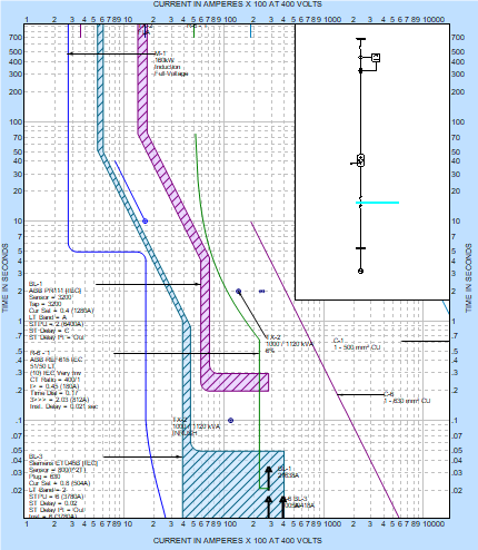
Figure 4: Relay Curve Clips at Remote Current
- Double-click on the green relay curve. A
Temporary Relay Data dialog box appears. Set the
TCC Clipping field to Use Steady State Current (see figure below). Click
OK.
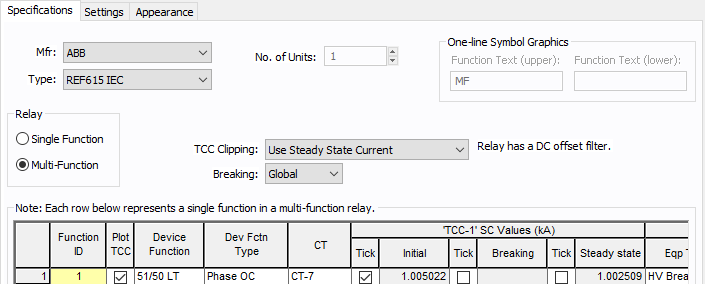
Figure 5: TCC Clipping Modification in the Temporary Relay Data Dialog
The relay curve now clips at the steady state fault current rather than the initial current. This provides increased flexibility and accuracy when determining the proper coordination settings for the relay.
Note: You might want to experiment with changing some of the other settings in the Temporary Relay Data dialog box. For example, typing in new Function ID names adds multiple function curves to the relay. In the Settings tab, the relay Instantaneous and Time Dial settings are modified. In the Appearance tab, you can change the curve colors and styles.
- In the TCC, click
 Fault Bus(es).
The maximum fault currents for each bus are shown.
Fault Bus(es).
The maximum fault currents for each bus are shown. - Click
 TCC Options. In the TCC Options dialog box, on the SC Control tab, select
User-Specified, and then click OK.
TCC Options. In the TCC Options dialog box, on the SC Control tab, select
User-Specified, and then click OK.
Notice the tick marks and clipping points also adjust in the TCC.
The TCC tick marks and clipping points update based on the user-specified currents in each protective device dialog box. For example, double-click on the blue solid state trip (SST) curve, select the Short Circuit tab, and notice the user-entered 22 kA.
Printing the TCC
While in the TCC, click
 Print. In the
Print TCC dialog box select one of the print options shown below and then click OK.
Print. In the
Print TCC dialog box select one of the print options shown below and then click OK.
The TCC plot prints WYSIWYG, or exactly what the screen displays. This provides tremendous speed and ease-of-use to the process of producing clean, professional printouts.
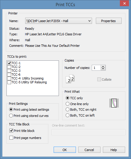
Figure 6: Print TCCs Dialog Box
TCC Dialog Boxes
To change protective device settings, double-click on any TCC curve or one-line item. This brings up a dialog box which enables you to change equipment settings and curve characteristics.
Note: The full list of cable, transformer, and motor parameters are available in the Database Edit focus. If you want to view these while in the TCC, right-click on the curve and select DB Info.
Creating and Storing TCCs
TCCs are created by selecting one-line equipment and clicking a button.
- From the Window button, select Protection-IEC.dez. This reactivates the main one-line window.
- Select a group of items by dragging a box around them or by holding down the SHIFT key while clicking the individual items, and then click
 Plot TCC. A new TCC window appears.
- Double-clicking on any TCC item or area displays the related temporary dialog box. In this manner, you can modify TCC curves, colors, notes, the title block, and other options as needed.
- When you have completed customizing the TCC, click Store TCC As. Type a name for the TCC, and then click OK.
Note: You can drag the text boxes to different locations to improve readability.
Conclusions
This has been a brief overview of the EasyPower PowerProtector™ coordination program. You might want to experiment with the other TCCs stored in the Protection-IEC.dez file. Also, other features are available in PowerProtector™ that were not discussed at length in this tutorial. A few are listed below:
- Fully user-definable EasyPower TCC curve library.
Note: The standard EasyPower library already has a full array of TCC curves, but an easy interface exists for curve entry if needed.
- Enhanced relay and CT graphics, including differential relays, ground CTs, and so on.
- Multi-function relays that plot multiple time-current curves.
- Full support of SST, non-SST, thermal magnetic, relay, and fuse protective device curves. The program also supports motor starting curves as well as cable and transformer damage curves.
- Time difference Indicator between TCC curves.
The EasyPower Help topics cover this and other features in greater
depth. To open Help, click  Help in the upper-right corner of the EasyPower window or press F1.