Tutorial - SmartDesign™
In this tutorial, we show you how to size components using EasyPower’s SmartDesign module. SmartDesign is an automated design tool for sizing switchgear, switchboards, panelboards, panels, MCC’s, conductors, breakers, fuses, and other electrical equipment for NEC compliance.
Before using SmartDesign, you need to completely model an entire system including motors and loads. A sample one-line has been created for this tutorial. Open the SmartDesign-1.dez file:
- From the File menu, click Open File.
- Open the SmartDesign-1.dez file in your Samples directory.
- Click
 Maximize on the one-line window, if needed, to fill the session window with the one-line.
Tip: If you are viewing the Start Page, you can click Open One-line instead.
Auto Design from the One-line
- Select transformer TX-1 and then on the Home tab, click
 Auto Design.
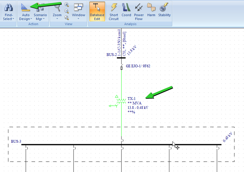
Figure 1: Auto Design One-line
- An Auto Design Report is created showing the new size of the transformer and the load data used for sizing.
To view the report, click
 Window, and then select Auto Design Report for [drive]:\...\SmartDesign-1.dez.
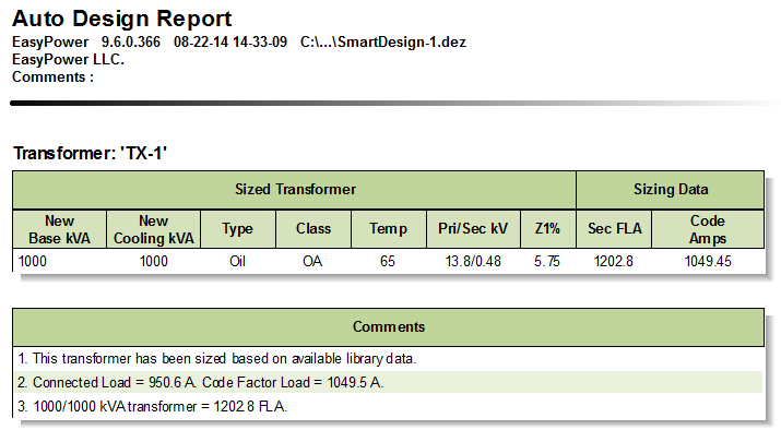
Figure 2: Auto Design Report
- Close the report, and then select all components downstream from the transformer and click
Auto Design.
Note: To select multiple equipment items on the one-line, hold down the SHIFT key while selecting each piece of equipment, or click and hold the left mouse button to drag a box around the equipment items you want to select.
- A new Auto Design Report is created, showing the new sizes of all the selected equipment and the load data used to size each equipment item. Select the report from under the Window button to view it.
Auto Design Options
To view the auto design options, click the arrow just below Auto Design and select
 Auto Design Options.
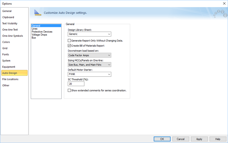
Figure 3: Auto Design Options
In the Auto Design tab of the Options dialog box, you can specify auto design settings for equipment sizing. These changes take effect on all subsequent sizing after you close the dialog box.
Auto Design MCCs and Panels
There are five different sizing options for MCCs and Panels. The option is selected in the Auto Design Options in the Sizing MCCs/Panels on One-line box, and include:
- Size Everything
- Size Bus, Main, and Main Feeders
- Size Bus and Main Only
- Size Bus Only
- Size Main Only
There are also 3 ways to size the MCC and panels on the one-line.
- Ribbon Method: Select the MCC or panel to be sized and then on the Home tab, click
Auto Design. This method uses the selected sizing option in
Auto Design Options under Sizing MCCs/Panels on One-line.
- Right-Click Method: When sizing an individual MCC or panel, the same sizing options listed above are available. Right-click on the MCC or panel, select
Auto Design, and then select the sizing option you want. This sizing method overrides the sizing option selected in the Auto
Design Options.
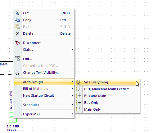
Figure 4: Sizing an MCC on the One-Line Using the Right-Click Context Menu
- Spreadsheet Method: The third method sizes the MCC or panel using the spreadsheet inside the equipment dialog box.
- Double-click on MCC-2_A and select the Description tab from MCC Data dialog box.
- Right-click on a row in the spreadsheet and select Auto-size Prot Device and Cable.
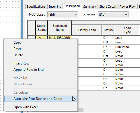
Figure 5: Sizing an Individual Row in the MCC Using the Spreadsheet
To view the Auto Design Report, on the Home tab, click Window, and then select the Auto Design Report for [drive]:\...\SmartDesign-1.dez report.
Library Modification
EasyPower performs auto design based on the design template in the library. You can modify the design style sheet in the EasyPower device library. The default design style sheet is titled “Generic.” Style sheets can be made for any type of design and using any manufacturer’s equipment.
- Click File > Open Library.
- Select the Stdlib.mdb file, and then click Open.
- In the library, select
Design > US > Generic in the tree view to open the design sheet.
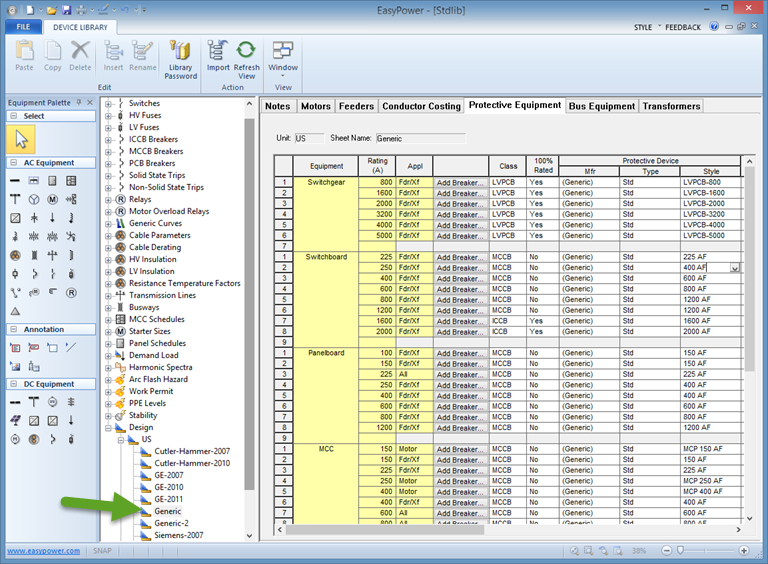
Figure 6: Library Auto Design Sheet Showing the Protective Equipment Tab
There are 7 tabs for each sheet containing user-definable sizing specifications that you can modify as needed. You can create additional design style sheets for multiple manufacturers, building types, or code zones. Design parameters are determined in Auto Design Options by selecting the appropriate Design Style Sheet.
Refer to the Customizing the Device Library topic in the EasyPower Help for more information.
Bill of Materials
A Bill of Materials Report is also created while auto designing, if this report is enabled in Auto Design Options.
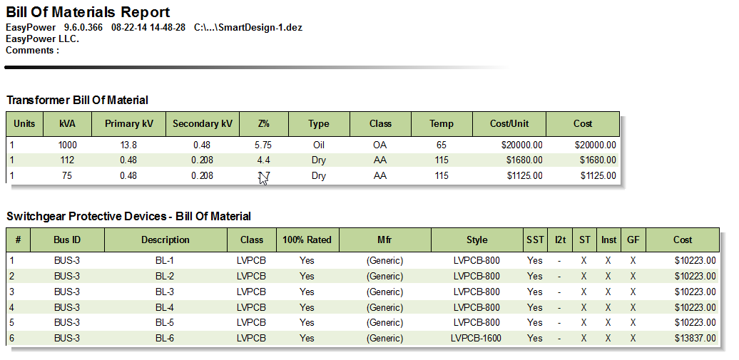
Figure 7: Bill of Materials Report
Conclusion
This has been a brief overview of EasyPower’s Auto Design feature. The EasyPower Help topics cover this and other features in greater
depth. To open Help, click  Help in the upper-right corner of the EasyPower window or press F1.