Run a Short Circuit Analysis
Open the Short Circuit Focus and Fault a Bus
Open the short circuit focus by clicking  Short Circuit on the Home tab.
Fault the lower right-hand bus by double-clicking on it. You should see the following results:
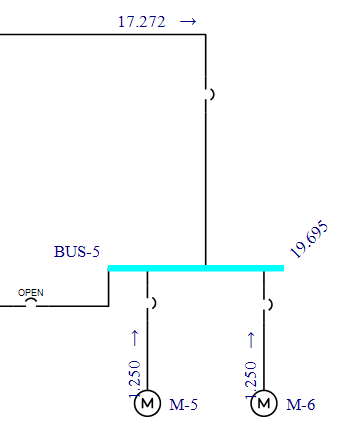
Figure 1: Running Short Circuit Analysis
Notice that we need to make a minor change to the one-line to see the results.
Adjusting the One-line for Results Readability
Drag each motor down enough that the numbers fit between it and the bus.
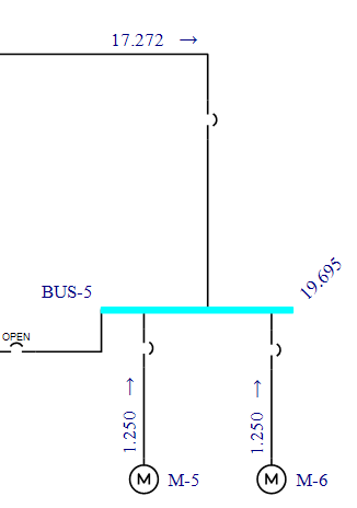
Figure 2: Readable Text After Adjusting One Line
After adjusting the one-line, you can save the updated arrangement with the Save command even though you are still in the short circuit focus.
Interpreting the Results
Note that the faulted bus is highlighted in blue. The default result units are symmetrical kilo-amps. (You can change this by clicking Tools > Short Circuit Options > One-line Output.) The faulted bus current is 19.490 kA, which is shown on the right-hand side of the bus at a forty-five degree angle. The contribution from the transformer is 17.066 kA, and the motor contribution is 1.250 kA.
If your results do not match these numbers, recheck the database dialog boxes for each item, comparing them to the dialog boxes shown in this tutorial. To do this, you must first get back to the Database Edit focus by clicking  Database Edit.
Looking at a Remote Voltage and Current
EasyPower gives you the ability to view remote voltages and currents (on multiple buses other than the one experiencing the fault).
While the lower right-hand bus is still faulted (highlighted in blue), click  Remote V/I on the Short Circuit tab to see the remote voltage and current for all remote buses.
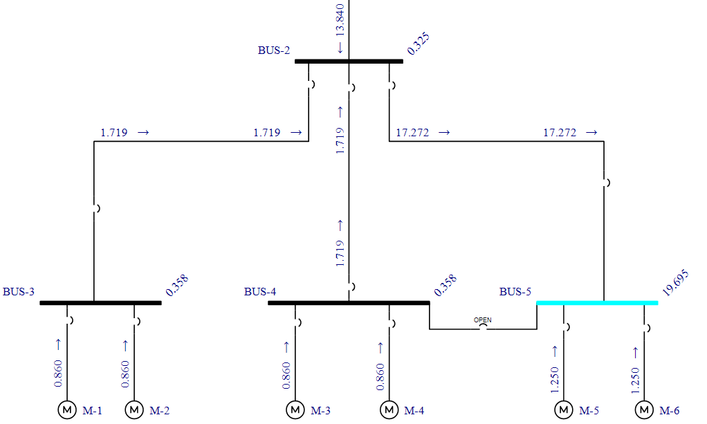
Figure 3: Looking at Remote Voltage and Current
As you can see, 0.86 kA from each of the motors flow to the fault on the right-hand bus. For remote buses, the voltage is shown at a forty-five degree angle. In this case, the value is 0.358 per unit, or about 35 percent of nominal. The voltage can be displayed in kV if desired by clicking SC Options > One-line Output.
Looking at Interrupting Results
Click  Interrupting on the Short Circuit tab to see the interrupting results. In addition to the half-cycle results, the interrupting (5-cycle) results also appear.
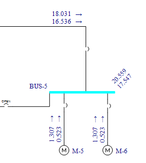
Figure 4: Viewing Interrupting Results
To see only the interrupting results, click  Momentary and turn the display off for momentary currents.
Notice that the motor contributions decay as the bus voltage is depressed and the time constants of the motors increase. This provides a clear indication of the currents necessary for setting relays.
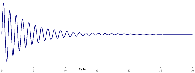
Figure 5: Motor Contribution to Short Circuit Current