Advanced Arc Flash Options
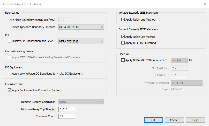
Figure 1: Advanced Arc Flash Options
| Option | Description |
|---|---|
|
Boundaries |
|
|
Arc Flash Boundary Energy (cal/cm2) |
The boundary is at a distance at which the incident energy is less than or equal to 1.2 cal/cm2. This is the default value. If the standard on the Arc Flash Hazard - Options tab is set to IEEE 1584-2018, you cannot change this. |
|
Shock Approach Boundary Distance |
Select the standard on which you want to specify approach boundaries. The options are:
|
| PPE | |
|
Display PPE Description and Level |
If this check box is selected, the PPE description and level is displayed on the one-line and the Arc Flash Hazard report. You can select which standard you want to use to specify the level. The levels are defined in the device library. See Defining PPE Levels for more information on customizing the levels. |
|
Current-Limiting Fuses |
|
|
Apply IEEE 1584 Current-Limiting Fuse Model Equations |
For the IEEE 1584-2018 standard, these calculations only apply when the electrode configuration is VCB. Use IEEE 1584 equations for current-limiting fuses to determine incident energy. This method calculates the let-through arc flash incident energy based on bolted fault currents and UL class of fuse. Equations are available for classes L and RK1. This is applicable only for low voltage systems. The fuse equations are effective only when the fault current is high compared to the minimum fault current required for limiting current. When the fault current is well below the current-limiting range of the fuse, the standard arc flash equations are used. When the 1584 CL Fuse Calculations are used for any bus, the Arc Flash Hazard Report shows the bolted fault current but not the arc current and the trip times, since these values are not used to determine the incident energy. Note: The IEEE 1584 CL fuse equations provide incident energy at 455mm. The default low voltage working distance in the program is 18 inches (which is equivalent to 457.2 mm). Therefore, the results for 18 inches will be slightly different from the results for 455mm. The current-limiting fuse calculations in IEEE 1584-2018 were based on testing performed using a 20 x 20 x 20 inch enclosure size. With the IEEE 1584-2018 equations, the 20 x 20 x 20 in. enclosure size results in the highest incident energy and arc flash boundary. All other enclosure sizes (smaller or larger) resulted in reduced incident energy and arc flash boundary. Therefore, application of current-limiting fuse calculations to all enclosure sizes is a conservative approach. |
|
DC Equipment |
|
|
Apply Low Voltage DC Equation to > 1 kV DC Equipment |
This option extends the low voltage DC equations to DC equipment in systems greater than 1 kV. |
|
Enclosure Size |
|
|
Apply Enclosure Size Correction Factor |
When selected, the arc flash calculations include the enclosure height, width, and depth (from either the library defaults or user-specified values) in the calculations. If this option is not selected, the library defaults or user-specified values are not used, and the enclosure size correction factor for IEEE 1584-2018 is set to 1. This applies to integrated and non-integrated calculation methods. |
|
Adjust IEEE Calculation Factor Based on Electrode Configuration |
Use this option to enable consideration of the electrode configuration in IEEE 1584-2002 arc flash calculations. A multiplier is applied to the calculation factor for VCBB and HCB electrode configurations not included in IEEE 1584-2002. |
|
Remote Current Calculation |
This option is set to Ratio if the standard on the Arc Flash Hazard - Options tab is set to IEEE 1584-2018. For the other standard options, EasyPower supports two different methods for determining the remote current through protective devices during an arc fault:
|
|
Minimum Relay Trip Time |
This is the minimum trip time used for relays. The default value is 0.016s. If the relay trip time in a TCC shows less than this specified value, this minimum time is used in arc flash. One-lines created in versions previous to 8.0.2.305 will show a minimum relay trip time of 0.01 seconds. You can change this option. |
|
Traverse Count |
This is the maximum number of buses the program will traverse upstream from the faulted bus to find the trip device. The default count is 12, to optimize for speed. You can increase the count value if necessary. Examples of where it may be necessary to increase the traverse count include long distribution feeders with multiple taps, busways (bus ducts) with multiple bus plugs, underground distribution systems, and wind farms. |
|
Voltage Exceeds IEEE Maximum |
|
|
Apply Ralph Lee Method |
You can apply the Ralph Lee method (default) or clear the check box to omit calculations. For arc flash standard NFPA 70E D.2 D.3, this setting is not applicable. |
|
Current Exceeds IEEE Maximum |
|
|
Apply Ralph Lee Method |
Use this option to select what happens when bolted fault currents exceed the limit of the IEEE 1584 model range.
For open air equipment, you can choose whether to apply the NFPA 70E 2009 Annex D.8 standard. You can select whether to apply that standard to greater than or equal to 1 kV or greater than 15 kV. Note: The NFPA 70E 2009 Annex D.8 option always overrides all other fault current calculation methods. |
|
Open Air |
|
|
Apply NFPA 70E 2009 Annex D.8 |
Enables calculations for open air buses based on NFPA 70E 2009 Annex D.8. That method describes estimating the incident energy for overhead open air systems from 1 kV to 800 kV. These calculations are based on open air phase-to-ground arcs. You can specify whether to calculate using this method beginning at 1 kV or 15 kV. For single-phase bus faults, open air high voltage arc flash calculations use the 70E-2009 Annex D.8 method taking the following approach:
|
|
3PH Multiplier |
This multiplier is used to estimate the incident energies for 3-phase faults for arcs on open air buses for the NFPA 70E 2009 Annex D.8 calculations. |
|
LL Multiplier |
This multiplier is used to estimate the incident energies for line-to-line faults for arcs on open air buses for the NFPA 70E 2009 Annex D.8 calculations |
|
Working Distances |
If there are user-specified working distances set up in the Bus Data dialog box, they override this setting. This setting controls what happens when the working distance has not been specified by the user.
|
|
Gaps |
Open air gaps are calculated based on NFPA 70E 2009 Annex D.8. |