|
Load Model
|
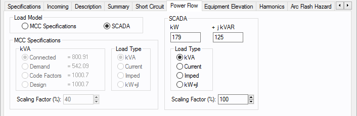
Enables you to select the motor kVA from the MCC Specifications data or from SCADA (Supervisory Control and Data Acquisition) data. SCADA data can be read in by clicking File > Import.
|
|
MCC Specifications
|
kVA: Select the method used to determine the kilovolt-ampere for power flow analysis. Choose between:
- Connected: The kVA is determined by the load defined on the Description tab of the MCC.
- Demand: The kVA is determined by the demand factor. Demand factor is calculated as the maximum loading conditions divided by the total connected load. This is specified on the Description tab of the MCC.
- Code: The kVA is determined by the code factors. Code factors are derived from the factors set up in the database File Properties on the Code Factors tab which reference NFPA 70 (NEC) article 220.40. You can view or edit the codes on the Description tab of the MCC.
- Design: The kVA is determined by the design factor in combination with the code factors. Design factor is set up in Tools > Options on the Equipment tab. You can view or edit the design factor on the Description tab of the MCC.
|
|
Load Type
|
Motors can be modeled for the power flow solution in several different ways.
- Constant kVA - This is the most common model. It is conservative, and results in slightly lower voltage values than would be measured on an actual system.
- Constant Current - This model is generally not used in motor modeling. It more closely matches an induction motor's characteristics in the reactive component than other models, but is technically incorrect because kW is relatively constant throughout the voltage range for an induction motor.
- Constant Impedance - This model is used for starting induction and synchronous machines, and closely matches motor characteristics during low voltages.
- kW + j Current - This model is a combination of the above models and more closely matches actual motor characteristics within normal operating voltages.
|
|
Scaling Factor
|
Provides an easy way of adjusting the total motor load used in determining power flows. By changing the scaling factor, the actual Hp (total connected value) entered in the Hp field can remain static. This reduces modeling errors and eliminates multiple databases for different contingencies.
|
|
SCADA Model
SCADA data is derived from real time, or metered data, and converted to an ASCII format which can be read into EasyPower. SCADA data is read in as a 100% scaling factor load. The load value is multiplied by the user-defined scaling factor. This provides a way to adjust SCADA loads to form new cases.
|
|
kW
|
The kW value as read in from the SCADA ASCII file.
|
|
kVAR
|
The kVAR value as read in from the SCADA ASCII file.
|
|
Load Type
|
SCADA data can be modeled in the power flow solution in several different ways. SCADA load type is set in the ASCII file, but can be changed by you.
- Constant kVA - This is the most common model. It is conservative, and results in slightly lower voltage values than would be measured on an actual system.
- Constant Current - This model is generally not used in motor modeling. It more closely matches an induction motor's characteristics in the reactive component than other models, but is technically incorrect because kW is relatively constant throughout the voltage range for an induction motor.
- Constant Impedance - This model is used for starting induction and synchronous machines, and closely matches motor characteristics during low voltages.
- kW + j Current - This model is a combination of the above models and more closely matches actual motor characteristics within normal operating voltages.
|
|
Scaling Factor
|
Provides an easy way of adjusting the total SCADA load used in determining power flows. By changing the scaling factor, the actual kW +j kVAR read in from the ASCII file remains static, however the load used in the power flow is adjusted by this factor.
|