Motor - TCC Tab
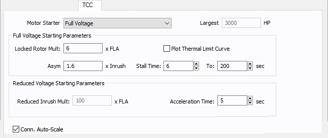
Figure 1: TCC tab of Motor Data Dialog Box
| Option | Description |
|---|---|
|
Provides a list of motor starters. Select the appropriate starter from the following:
|
|
|
Largest |
In grouped motor data, you can specify the size of the largest motor. This field is unavailable when you select the motor as individual motor. When you plot the motor starting curve on a time-current curve (TCC), the program plots the curve such that the largest motor is being started and the rest of the motors in the group are running at full load. |
|
Full Voltage Starting Parameters This section specifies the motor current characteristics during starting at the rated motor voltage. |
|
| Locked Rotor Multiple | Locked rotor current as multiples of full load amps. |
|
Asymmetrical (Asym) Offset |
Factor by which the inrush current is higher due to the asymmetry current. |
|
Check box to plot thermal limit time-current curve of the motor. The curve is shown within the limits of the Stall Time described below. The curve is an I2t curve passing through the Stall Time and the locked rotor amps. |
|
|
Stall Time |
The maximum time in seconds that the motor can safely withstand stalling. |
|
To |
The maximum time in seconds of the thermal limit curve of the motor you want to plot. |
|
Reduced Voltage Starting Parameters |
Specifies the starting time and the current or voltage ratio under reduced voltage. Depending upon the motor starter type selected enter one of the following. The starting current will be calculated from this.
|
|
Acceleration Time |
The starting time in seconds. |
|
Conn. Auto-Scale |
When this check box is selected, the program automatically scales the TCC curves based on the phase connection type. Traditionally, for 3PH curves in a TCC, scaling the curves based on the reference voltage is adequate. If a line-to-neutral connected 1PH device is to be plotted with an upstream 3PH device, then the LN connected 1PH curve needs to be shifted by a factor of the SQRT(3) in addition to the voltage-based scaling. Similarly, if a line-to-neutral connected 1PH device is to be plotted with an upstream 1PH-3W device, then the LN connected 1PH curve needs to be shifted by a factor of the 2 in addition to the voltage-based scaling.When the check box is not selected, scaling based on the phase connection type is not applied. The check box status for individually stored TCC plots can be different. The default for new TCC plots is obtained from the database for the device. |
More Information
- Motor Data
- Database Dialog Box Toolbar
- Motor - Connection Information
- Motor - Specifications Tab
- Motor - Short Circuit Tab
- Motor - Power Flow Tab
- Motor - Motor Starting Tab
- Motor - Harmonics Tab
- Motor - Stability Tab
- Motor - Reliability Tab
- Motor - Location Tab
- Motor - Comments Tab
- Motor - Hyperlinks Tab
- Motor - Collected Data Tab
- Motor - Media Gallery Tab